SERIES IOS-320 I/O SERVER MODULE 12-BIT HIGH DENSITY ANALOG INPUT BOARD
__________________________________________________________________________________________
- 7 -
Acromag, Inc. Tel:248-295-0310 Fax:248-624-9234 Email:solutions@acromag.com http://www.acromag.com
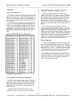
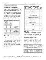
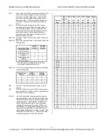
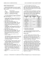
Bit 15: When read, the CTRIG bit indicates whether an ADC
conversion has been triggered, either by software
command or external trigger input. If the bit reads
high, the conversion could be taking place or has
been completed. CTRIG is cleared by reading the
ADC data. Writing to this bit position will have no
effect.
Bit 14:
The Data Ready bit indicates if an ADC convert
command has completed and valid data resides in
the ADC Data Register. If the bit reads high, then
valid data awaits in the ADC data register from the
previous conversion. Data Ready is cleared by
reading the ADC data register. Writing to this bit
position will have no effect.
Bits 13-10: Not used - if read will return data written to those bit
positions.
Bits 9 & 8: Control the input acquisition mode as described in the
following table:
Acquisition Mode
MODE1
Bit (D09)
MODE0
Bit (D08)
Differential Input
CH0-19 & CAL0-3
0
0
Single-ended Input
CH0-19
0
1
Single-ended Input
CH20-39
1
0
Auto Zero Input*
1
1
* Auto Zero input is enabled by the mode bits,
overriding all channel selection bits.
Bits 7 & 6: Control the programmable gain setting as described
in the following table:
Desired Gain
Setting
GSEL1
Bit (D07)
GSEL0
Bit (D06)
1
0
0
2
0
1
4
1
0
8
1
1
Bit 5: Not used - if read will return data written to the bit
position.
Bit 4: The SEL HIGH bit acts as the MSB for analog input
channel selection. As such, its action is grouped with
that of bits 3-0 (see following).
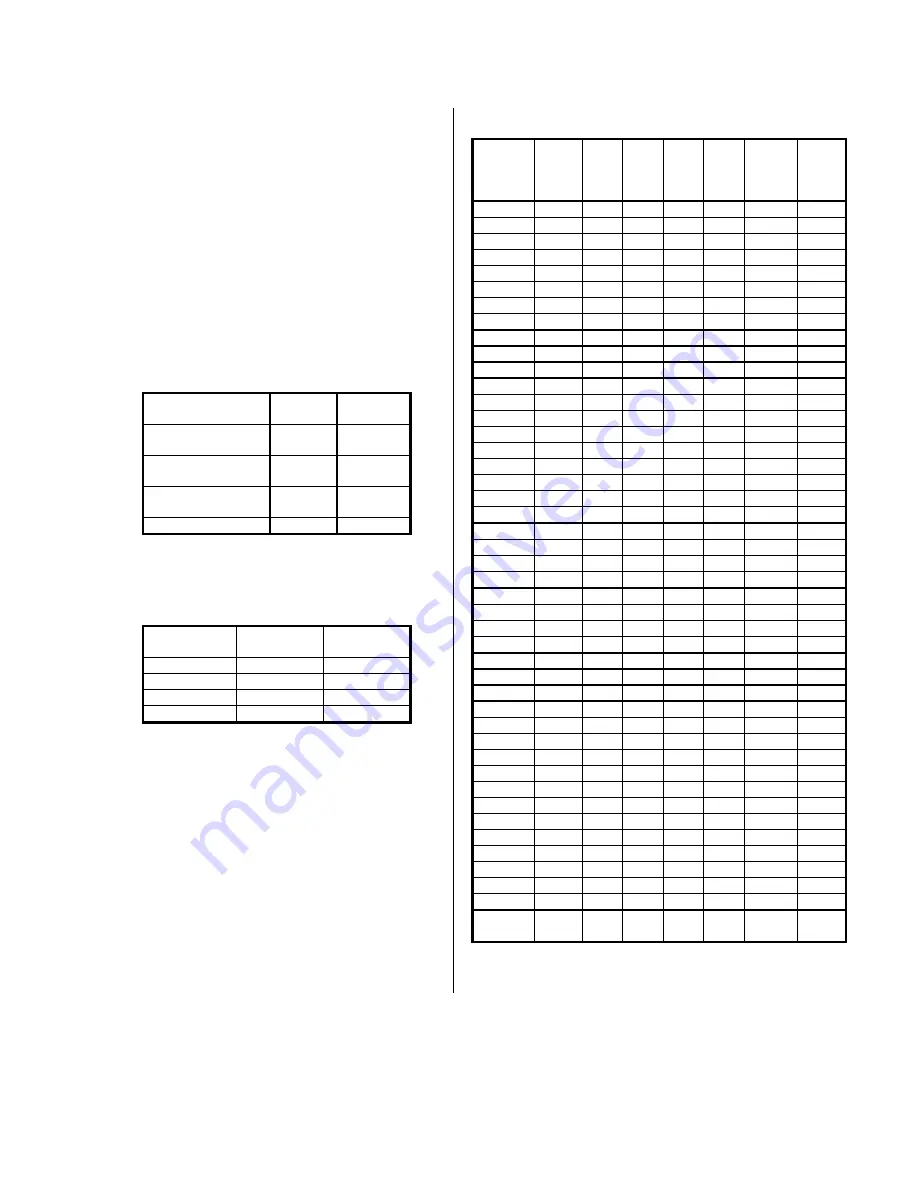
Bits 3-0: Control the selection of analog input channels per
the following table. Note that the SEL HIGH bit and
MODE bits are also shown to completely define the
channel selection. When MODE 1 & MODE 0 are
both 0, differential channels 0-19 and calibration
voltages 0-3 may be selected; when MODE 1 is 0
and MODE 0 is 1, single-ended channels 0-19 may
be selected; when MODE 1 is 1 and MODE 0 is 0,
single-ended channels 20-39 may be selected; when
both MODE 1 & MODE 0 are 1, the Auto Zero input
is selected regardless of any other bit levels.
Desired
Chan.
SEL
HIGH
Bit
D04
CH3
Bit
D03
CH2
Bit
D02
CH1
Bit
D01
CH0
Bit
D00
Mode
1
Bit
D09
Mode
0
Bit
D08
0
0
0
0
0
0
0
0/1
1
0
0
0
0
1
0
0/1
2
0
0
0
1
0
0
0/1
3
0
0
0
1
1
0
0/1
4
0
0
1
0
0
0
0/1
5
0
0
1
0
1
0
0/1
6
0
0
1
1
0
0
0/1
7
0
0
1
1
1
0
0/1
8
0
1
0
0
0
0
0/1
9
0
1
0
0
1
0
0/1
10
0
1
0
1
0
0
0/1
11
0
1
0
1
1
0
0/1
12
0
1
1
0
0
0
0/1
13
0
1
1
0
1
0
0/1
14
0
1
1
1
0
0
0/1
15
0
1
1
1
1
0
0/1
16
1
0
0
0
0
0
0/1
17
1
0
0
0
1
0
0/1
18
1
0
0
1
0
0
0/1
19
1
0
0
1
1
0
0/1
CAL0
1
0
1
0
0
0
0
CAL1
1
0
1
0
1
0
0
CAL2
1
0
1
1
0
0
0
CAL3
1
0
1
1
1
0
0
20
0
0
0
0
0
1
0
21
0
0
0
0
1
1
0
22
0
0
0
1
0
1
0
23
0
0
0
1
1
1
0
24
0
0
1
0
0
1
0
25
0
0
1
0
1
1
0
26
0
0
1
1
0
1
0
27
0
0
1
1
1
1
0
28
0
1
0
0
0
1
0
29
0
1
0
0
1
1
0
30
0
1
0
1
0
1
0
31
0
1
0
1
1
1
0
32
0
1
1
0
0
1
0
33
0
1
1
0
1
1
0
34
0
1
1
1
0
1
0
35
0
1
1
1
1
1
0
36
1
0
0
0
0
1
0
37
1
0
0
0
1
1
0
38
1
0
0
1
0
1
0
39
1
0
0
1
1
1
0
Auto
Zero
X
X
X
X
X
1
1

