SERIES IP1K110 INDUSTRIAL I/O PACK RECONFIGURABLE DIGITAL I/O MODULE
__________________________________________________________________________________________
- 4 -
Acromag, Inc. Tel:248-295-0310 Fax:248-624-9234 Email:solutions@acromag.com
http://www.acromag.com
IP MODULE Win32 DRIVER SOFTWARE
Acromag provides a software product (sold separately) to
facilitate the development of Windows (2000/XP/Vista/7
)
applications accessing Industry Pack modules installed on
Acromag PCI Carrier Cards and CompactPCI Carrier Cards.
This software (Model IPSW-API-WIN) consists of low-level
drivers and Windows 32 Dynamic Link Libraries (DLLS) that are
compatible with a number of programming environments
including Visual C++, Visual Basic, Borland C++ Builder and
others. The DLL functions provide a high-level interface to the
carriers and IP modules eliminating the need to perform low-level
reads/writes of registers, and the writing of interrupt handlers.
IP MODULE VxWORKS SOFTWARE
Acromag provides a software product (sold separately)
consisting of IP module VxWorks
libraries. This software
(Model IPSW-API-VXW MSDOS format) is composed of
VxWorks
(real time operating system) libraries for all Acromag
IP modules and carriers. The software is implemented as a
library of “C” functions which link with existing user code to make
possible simple control of all Acromag IP modules and carriers.
The IP1K110 support programs implement the transfer of
developed code between the user’s processor and the Altera
FPGA.
2.0 PREPARATION FOR USE
UNPACKING AND INSPECTION
Upon receipt of this product, inspect the shipping carton for
evidence of mishandling during transit. If the shipping carton is
badly damaged or water stained, request that the carrier's agent
be present when the carton is opened. If the carrier's agent is
absent when the carton is opened and the contents of the carton
are damaged, keep the carton and packing material for the
agent's inspection.
For repairs to a product damaged in shipment, refer to the
Acromag Service Policy to obtain return instructions. It is
suggested that salvageable shipping cartons and packing
material be saved for future use in the event the product must be
shipped.
This board is physically protected
with packing material and electrically
protected with an anti static bag
during shipment. However, it is
recommended that the board be
visually inspected for evidence of
mishandling prior to applying power.
The board utilizes static sensitive
components and should only be
handled at a static-safe workstation.
CARD CAGE CONSIDERATIONS
Refer to the specifications for loading and power
requirements. Be sure that the system power supplies are able
to accommodate the power requirements of the carrier board,
plus the installed IP modules, within the voltage tolerances
specified.
IMPORTANT
: Adequate air circulation must be provided to
prevent a temperature rise above the maximum operating
temperature.
The dense packing of the IP modules to the carrier board
restricts air flow within the card cage and is cause for concern.
Adequate air circulation must be provided to prevent a
temperature rise above the maximum operating temperature and
to prolong the life of the electronics. If the installation is in an
industrial environment and the board is exposed to environmental
air, careful consideration should be given to air-filtering.
BOARD CONFIGURATION
Power should be removed from the board when installing IP
modules, cables, termination panels, and field wiring. Refer to
Mechanical Assembly Drawing 4501-434 and the following
discussion for configuration and assembly instructions. Model
IP1K110 I/O Boards have no jumpers or switches to configure—
all configuration is through software commands.
CONNECTORS
IP Field I/O Connector (P2)
P2 provides the field I/O interface connector for mating IP
modules to the carrier board. P2 is a 50-pin female receptacle
header (AMP 173279-3 or equivalent) which mates to the male
connector of the carrier board (AMP 173280-3 or equivalent).
This provides excellent connection integrity and utilizes gold-
plating in the mating area. Threaded metric M2 screws and
spacers are supplied with the module to provide additional
stability for harsh environments (see Mechanical Assembly
Drawing 4501-434). The field and logic side connectors are
keyed to avoid incorrect assembly.
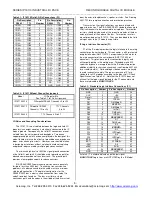
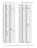
P2 pin assignments are unique to each IP model (see Table
2.1) and normally correspond to the pin numbers of the field-I/O
interface connector on the carrier board (you should verify this for
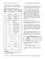
your carrier board). When reading Table 2.1 notice that RS485
input/output channels as well as digital TTL input/output channels
are listed with their corresponding connector pin number. Each
I/O point will be either RS485 or TTL defined by your IP1K110
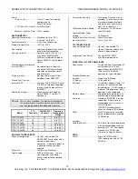
model. Table 2.2 lists the channels dedicated to each of the
IP1K110 models.


