SERIES IP330 INDUSTRIAL I/O PACK 16-BIT HIGH DENSITY ANALOG INPUT MODULE
___________________________________________________________________________________________
- 21 -
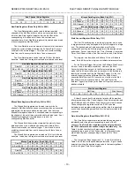
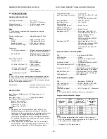
Maximum Overall Calibrated Error @ 25
°
C
The maximum corrected (i.e. calibrated) error is the worst case
accuracy possible. It is the sum of error components due to ADC
quantization of the low and high calibration signals, PGA and ADC
linearity error, and the absolute errors of the recommended
calibration voltages at 25oC.
Input
Range
(Volts)
PGA
Gain
ADC
Range
(Volts)
Max. Err
7,8,10
±
LSB
(% Span)
Typ. Err
7,8,10
±
LSB
(% Span)
-5 to +5
1
-5 to +5
8.6 LSB
(0.013%)
2 LSB
(0.003%)
Note:
7. A total of 256 input samples, autozero values, and calibration
voltages were averaged with a throughput Rate of 67khz
conversions/second. Follow the input connection
recommendations of Section 2, because input noise and non-
ideal grounds can degrade overall system accuracy. For
critical applications multiple input samples should be averaged
to improve performance. Accuracy versus temperature
depends on the temperature coefficient of the calibration
voltage.
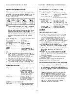
Settling Time (20V step)
8
...............3.5uS to 0.01%, Typical (PGA).
A/D Conversion Time.....................8uS Maximum
Conversion Rate............................125KHz Maximum
Recommended Conversion Rate
8
..67KHz.
A/D Triggers..................................External and Software.
Input Noise
8,9
.................................2 LSB rms, Typical.
Temperature Coefficient................See spec of calibration
voltages.
Interrupt..........................................Vectored Interrupt on end
channel conversion or end of
group of channel conversions.
Note:
8. Reference Test Conditions: Differential inputs,
±
5V input
range, PGA Gain = 1, Temperature 25
°
C,
±
12V internal power
supplies, 67K conversions/second, using Acromag’s
AVME9660 VMEbus IP carrier with a 5 inch shielded cable
length connection to the field analog input signals.
9. A total of 2048 input samples were taken statistically,
assuming a normal distribution, to determine the RMS value.
10. Accuracy may be further improved by increasing the time
between conversions (e.g. from 15
µ
seconds to 30
µ
seconds).
External Trigger Input/Output
As An Input:...............................Must be an active low 5 volt logic
TTL compatible, debounced
signal referenced to analog
common. Conversions are
triggered on the falling edge of
this trigger signal. Minimum
pulse width 500n seconds
As An Output:......................... ...Active low 5 volt logic TTL
compatible output is generated.
The trigger pulse is low for a
maximum of 500n seconds.
INDUSTRIAL I/O PACK COMPLIANCE
Specification................................This module meets or exceeds
all written Industrial I/O Pack
specifications per revision 0.7.1.
Electrical/Mechanical Interface....Single-Size IP Module.
IP Data Transfer Cycle Types Supported:
Input/Output (IOSel*)............D16 or D08 read/write of data.
ID Read (IDSel*)...................32 x 8 ID PROM read on D0..D7.
as D16 or D08.
Interrupt Select (INTSel*)......8-bits (D08)
Interrupt Vector Register contents.
Access Times (8MHz Clock):
ID PROM Read....................1 wait state (375ns cycle).
I/O Space Read...................1 wait state (375ns cycle).
Mail Box I/O Space Read 1 wait state typical (375ns cycle)
6 wait states maximum if ongoing
internal Mail Box write.
I/O Space Write....................1 wait state (375ns cycle).
Interrupt Select Read............1 wait state (375ns cycle).
APPENDIX
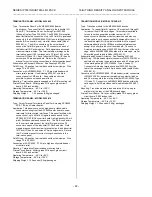
CABLE: MODEL 5025-551-x (Shielded)
Type: Flat Ribbon Cable, 50-wires (female connectors at both
ends). The ‘-x’ suffix designates the length in feet (12 feet
maximum). Choose shielded cable according to model
number. The shielded cable is highly recommended for
optimum performance with IP330 analog input module.
Application: Used to connect a Model 5025-552 termination panel
to the AVME9630/9660 non-intelligent carrier board A-D
connectors (both have 50-pin connectors).
Length: Last field of part number designates length in feet (user-
specified, 12 feet maximum). It is recommended that this
length be kept to a minimum to reduce noise and power loss.
Cable: 50-wire flat ribbon cable, 28 gage. Shielded cable model
uses Acromag Part 2002-261 (3M Type 3476/50 or
equivalent).
Headers (Both Ends): 50-pin female header with strain relief.
Header -
Acromag Part 1004-512 (3M Type 3425-6600 or
equivalent).
Strain Relief -
Acromag Part 1004-534 (3M Type
3448-3050 or equivalent).
Keying: Headers at both ends have polarizing key to prevent
improper installation.
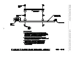
Schematic and Physical Attributes: See Drawing 4501-463.
Shipping Weight: 1.0 pound (0.5Kg) packaged.
RECOMMENDED SHIELDED CABLE (APC8600 High-Density)
A shielded cable for use with the APC8600 PC carrier is not
available directly from Acromag but is strongly recommended.
The following vendors’ shielded ribbon cable and connector
part number information is provided to facilitate construction of
your own shielded cables.
Connector:
The connector is a 50-pin, high-density (25mil
pitch), female receptacle header (T& B Ansley Part 311-
050302 or equivalent). The connector mates to the male
connector (T&B Ansley Part 311-050072E or equivalent) on
the APC8600 carrier board at one end of the cable and the
APC8600 termination panel at the other end of the cable.
Cable:
50-wire flat ribbon cable, 30 gage, Shielded
(T&B/Ansley Part 188-050 or equivalent).


