SERIES IP400 INDUSTRIAL I/O PACK 40-CHANNEL DIGITAL INPUT MODULE
___________________________________________________________________________________________
-10-
APPENDIX
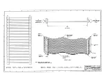
CABLE: MODEL 5025-550-x (Non-Shielded)
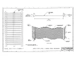
MODEL 5025-551-x (Shielded)
Type: Flat Ribbon Cable, 50-wires (female connectors at both
ends). The ‘-x’ suffix designates the length in feet (12 feet
maximum). Choose shielded or unshielded cable according to
model number. The unshielded cable is recommended for
digital I/O, while the shielded cable is recommended for
optimum performance with precision analog I/O applications.
Application: Used to connect a Model 5025-552 termination panel to
the AVME9630/9660 non-intelligent carrier board A-D
connectors (both have 50-pin connectors).
Length: Last field of part number designates length in feet (user-
specified, 12 feet maximum). It is recommended that this length
be kept to a minimum to reduce noise and power loss.
Cable: 50-wire flat ribbon cable, 28 gage. Non-Shielded cable
model uses Acromag Part 2002-211 (3M Type C3365/50 or
equivalent). Shielded cable model uses Acromag Part 2002-261
(3M Type 3476/50 or equivalent).
Headers (Both Ends): 50-pin female header with strain relief.
Header - Acromag Part 1004-512 (3M Type 3425-6600 or
equivalent). Strain Relief - Acromag Part 1004-534 (3M Type
3448-3050 or equivalent).
Keying: Headers at both ends have polarizing key to prevent
improper installation.
Schematic and Physical Attributes: For Non-Shielded cable model,
see Drawing 4501-462. For Shielded cable model, see Drawing
4501-463.
Shipping Weight: 1.0 pound (0.5Kg),packaged.
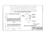
TERMINATION PANEL: MODEL 5025-552
Type: Termination Panel For AVME9630/9660 Boards
Application: To connect field I/O signals to the Industrial I/O Pack
(IP). Termination Panel: Acromag Part 4001-040 (Phoenix
Contact Type FLKM 50). The 5025-552 termination panel
facilitates the connection of up to 50 field I/O signals and
connects to the AVME9630/9660 3U/6U non-intelligent carrier
boards (A-D connectors only) via a flat ribbon cable (Model
5025-550-x or 5025-551-x). The A-D connectors on the carrier
board connect the field I/O signals to the P2 connector on each
of the Industrial I/O Pack modules. Field signals are accessed
via screw terminal strips. The terminal strip markings on the
termination panel (1-50) correspond to P2 (pins 1-50) on the
Industrial I/O Pack (IP). Each Industrial I/O Pack (IP) has its
own unique P2 pin assignments. Refer to the IP module manual
for correct wiring connections to the termination panel.
Schematic and Physical Attributes: See Drawing 4501-464.
Field Wiring: 50-position terminal blocks with screw clamps. Wire
range 12 to 26 AWG.
Connections to AVME9630/9660: P1, 50-pin male header with
strain relief ejectors. Use Acromag 5025-550-x or 5025-551-x
cable to connect panel to VME board. Keep cable as short as
possible to reduce noise and power loss.
Mounting: Termination panel is snapped on the DIN mounting rail.
Printed Circuit Board: Military grade FR-4 epoxy glass circuit board,
0.063 inches thick.
Operating Temperature: -40
°
C to +100
°
C.
Storage Temperature: -40
°
C to +100
°
C.
Shipping Weight: 1.25 pounds (0.6kg) packaged.
TRANSITION MODULE: MODEL TRANS-GP
Type: Transition module for AVME9630/9660 boards.
Application: To repeat field I/O signals of IP modules A through D
for rear exit from VME card cages. This module is available for
use in card cages which provide rear exit for I/O connections via
transition modules (transition modules can only be used in card
cages specifically designed for them). It is a double-height
(6U), single-slot module with front panel hardware adhering to
0the VMEbus mechanical dimensions, except for shorter printed
circuit board depth. Connects to Acromag termination panel
5025-552 from the rear of the card cage, and to
AVME9630/9660 boards within card cage, via flat 50-pin ribbon
cable (cable Model 5025-550-X or 5025-551-X).
Schematic and Physical Attributes: See Drawing 4501-465.
Field Wiring: 50-pin header (male) connectors (3M 3433-D303 or
equivalent) employing long ejector latches and 30 micron gold in
the mating area (per MIL-G-45204, Type II, Grade C).
Connects to Acromag termination panel 5025-552 from the rear
of the card cage via flat 50-pin ribbon cable (cable Model
5025-550-X or 5025-551-X).
Connections to AVME9630/9660: 50-pin header (male) connectors
(3M 3433-1302 or equivalent) employing long ejector latches
and 30 micron gold in the mating area (per MIL-G-45204, Type
II, Grade C). Connects to AVME9630/9660 boards within the
card cage via flat 50-pin ribbon cable (cable Model 5025-550-X
or 5025-551-X).
Mounting: Transition module is inserted into a 6U-size, single-width
slot at the rear of the VMEbus card cage.
Printed Circuit Board: Six-layer, military-grade FR-4 epoxy glass
circuit board, 0.063 inches thick.
Operating Temperature: -40
°
C to +85
°
C.
Storage Temperature: -55
°
C to +105
°
C.
Shipping Weight: 1.25 pounds (0.6Kg) packaged.


