SERIES IP400 INDUSTRIAL I/O PACK 40-CHANNEL DIGITAL INPUT MODULE
___________________________________________________________________________________________
-3-
•
Supports 16-bit & 8-bit I/O - Channel register Read/Write is
performed through 16-bit (D16) or 8-bit (D08[EO]) data transfer
cycles in the IP module I/O space.
•
High Speed - Acquisition times for all data transfer cycles are
described in terms of "wait" states - 1 wait state is required for
reading the inputs, 1 wait state for write operations (see
specifications for detailed information).
SIGNAL INTERFACE PRODUCTS
(See Appendix for more information on compatible products)
This IP module will mate directly to any industry standard IP
carrier board (including Acromag AVME9630/9660 3U/6U non-
intelligent carrier boards). Consult the documentation of your carrier
board to ensure compatibility with the following interface products
(since all connections to field signals are made through the carrier
board which passes them to the individual IP modules).
Cables:
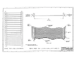
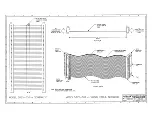
Model 5025-551-X (Shielded Cable), or Model 5025-550-X
(Non-Shielded Cable): A Flat 50-pin cable with female
connectors at both ends for connecting AVME9630/9660, or
other compatible carrier boards, to Model 5025-552 termination
panels. The “X” of Model denotes the length in feet. The
unshielded cable is recommended for digital I/O, while the
shielded cable is recommended for optimum performance with
precision analog I/O applications.
Termination Panel:
Model 5025-552: A DIN-rail mountable panel that provides 50
screw terminals for universal field I/O termination. Connects to
Acromag AVME9630/9660, or other compatible carrier boards,
via flat 50-pin ribbon cable (Model 5025-550-X or 5025-551-X).
Transition Module:
Model TRANS-GP: This module repeats field I/O connections
of IP modules A through D for rear exit from the card cage. It is
available for use in card cages which provide rear exit for I/O
connections via transition modules (transition modules can only
be used in card cages specifically designed for them). It is a
double-height (6U), single-slot module, with front panel
hardware adhering to the VMEbus mechanical dimensions,
except for shorter printed circuit board depth. It connects to
Acromag Termination Panel 5025-552 from the rear of the card
cage, and to AVME9630/9660 boards within the card cage, via
flat 50-pin ribbon cable (Model 5025-550-X or 5025-551-X).
INDUSTRIAL I/O PACK SOFTWARE LIBRARY
Acromag provides an Industrial I/O Pack Software Library
diskette (Model IPSW-LIB-M03, MSDOS format) to simplify
communication with the board. All functions are written in the “C”
programming language and can be linked to your application. Refer
to the “README.TXT” file in the root directory and the
“INFO400.TXT” file in the “IP400” subdirectory on the diskette for
more details.
2.0 PREPARATION FOR USE
UNPACKING AND INSPECTION
Upon receipt of this product, inspect the shipping carton for
evidence of mishandling during transit. If the shipping carton is
badly damaged or water stained, request that the carrier's agent be
present when the carton is opened. If the carrier's agent is absent
when the carton is opened and the contents of the carton are
damaged, keep the carton and packing material for the agent's
inspection.
For repairs to a product damaged in shipment, refer to the
Acromag Service Policy to obtain return instructions. It is
suggested that salvageable shipping cartons and packing material
be saved for future use in the event the product must be shipped.
This board is physically protected with
packing material and electrically
protected with an anti-static bag during
shipment. However, it is recommended
that the board be visually inspected for
evidence of mishandling prior to
applying power.
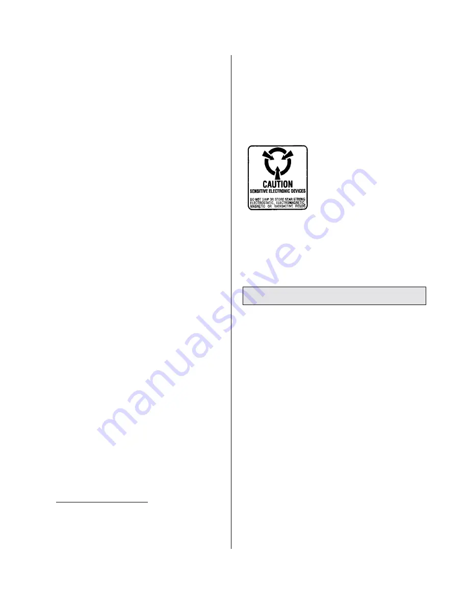
The board utilizes static sensitive
components and should only be
handled at a static-safe workstation.
CARD CAGE
CONSIDERATIONS
Refer to the specifications for loading and power requirements.
Be sure that the system power supplies are able to accommodate
the power requirements of the carrier board, plus the installed IP
modules, within the voltage tolerances specified.
IMPORTANT: Adequate air circulation must be provided to prevent
a temperature rise above the maximum operating temperature.
The dense packing of the IP modules to the carrier board
restricts air flow within the card cage and is cause for concern.
Adequate air circulation must be provided to prevent a temperature
rise above the maximum operating temperature and to prolong the
life of the electronics. If the installation is in an industrial
environment and the board is exposed to environmental air, careful
consideration should be given to air-filtering.
BOARD CONFIGURATION
Power should be removed from the board when installing IP
modules, cables, termination panels, and field wiring. Refer to
Mechanical Assembly Drawing 4501-434 and your IP module
documentation for configuration and assembly instructions. Model
IP400 Input Boards have no jumpers or switches to configure--
interrupts are configured through software command.
CONNECTORS
IP Field I/O Connector (P2)
P2 provides the field I/O interface connector for mating IP
modules to the carrier board. P2 is a 50-pin female receptacle
header (AMP 173279-3 or equivalent) which mates to the male
connector of the carrier board (AMP 173280-3 or equivalent). This
provides excellent connection integrity and utilizes gold-plating in the
mating area. Threaded metric M2 screws and spacers are supplied
with the module to provide additional stability for harsh environments
(see Mechanical Assembly Drawing 4501-434). The field and logic
side connectors are keyed to avoid incorrect assembly.


