IP482 Industrial I/O Pack User’s Manual Counter Timer Module
___________________________________________________________________
________________________________________________________________________________________
Acromag, Inc. Tel:248-295-0310 Fax:248-624-9234 Email:solutions@acromag.com http://www.acromag.com
21
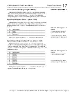
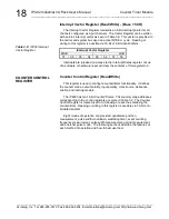
The Counter Control register bits 11 and 10 are used to control the
operation of the counter output signal. With bits 11 and 10 set to “01”, the
output signal will be driven active while the counter equals the counter
Constant A value. With bit 11 set to logic “1” the output signal will be driven
active while the index condition remains true.
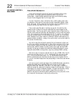
Encoder output signals can be noisy. It is recommended that the InA,
InB, and InC input signals be debounced by setting bit-13 of the Counter
Control register to logic “1”. Noise transitions less than 2.5
s will be
removed with debounce enabled.
COUNTER CONTROL
REGISTER
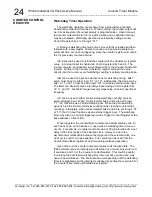
QUADRATURE
POSITION
MEASUREMENT


