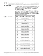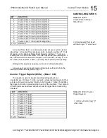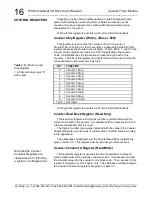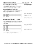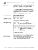
IP482 Industrial I/O Pack User’s Manual Counter Timer Module
___________________________________________________________________
________________________________________________________________________________________
Acromag, Inc. Tel:248-295-0310 Fax:248-624-9234 Email:solutions@acromag.com http://www.acromag.com
25
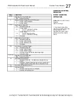
Bit(s)
FUNCTION
2,1,0
Specifies the Counter Mode:
011
Watchdog Function
3
Output Polarity (Output Pin ACTIVE Level):
0
Active LOW (Default)
1
1
Active HIGH
5, 4
InA Polarity / Counter Reload
00
Disabled (Default)
01
Active LOW
In A=0 Counter Reinitialized
In A=1 Inactive State
10
Active HIGH
In A=0 Inactive State
In A=1 Counter Reinitialized
11
Disabled
7, 6
InB Polarity / External Clock Input
00
Disabled (Default)
01
External Clock Enabled
10
External Clock Enabled
11
Disabled
9,8
InC Polarity / External Trigger
00
Disabled (Default)
01
Active LOW Trigger
10
Active HIGH Trigger
11
Gate-Off (Continue when high/Stop when low)
12,11,10
Clock Source
2
Carrier Operational Freq.
8MHz
32MHz
000
Internal @ (Default)
0.5MHz
2MHz
001
Internal @
1MHz
4MHz
010
Internal @
2MHz
8MHz
011
Internal @
4MHz
16MHz
100
Internal @
8MHz
32MHz
101
External Clock
Up to 2MHz
Up to 8MHz
13
Input Debounce Enable
0
Disabled (Default)
– No Debounce Applied to any
Input.
1
Enabled
– Reject Reinitialize or Trigger Pulses
(noise) less than or equal to 2.5
s.
14
Not Used (bit reads back as 0)
15
Interrupt Enable
0
Disable Interrupt Service (Default)
1
Enable Interrupt Service
WATCHDOG TIMER
OPERATION
COUNTER CONTROL
REGISTER
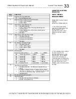
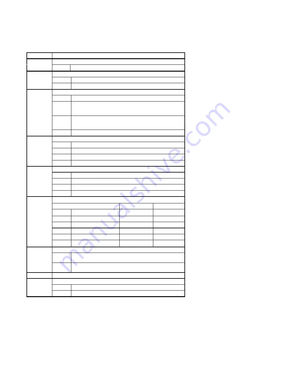
Table 3.12:
Counter Control
Register (Watchdog Timer)
1. The default state of the
output pin is high (output has
pullup installed). Bit 3
specifies the active output
polarity when the output is
driven.
2. The available clock sources
are determined by the
operational frequency of the
carrier board. For an 8MHz
carrier, bit 0 of the Board
Control Register located at the
base address plus an offset of
0H must be set low. For a
32MHz carrier, the bit must be
set high.


