IP482 Industrial I/O Pack User’s Manual Counter Timer Module
___________________________________________________________________
________________________________________________________________________________________
Acromag, Inc. Tel:248-295-0310 Fax:248-624-9234 Email:solutions@acromag.com http://www.acromag.com
9
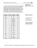
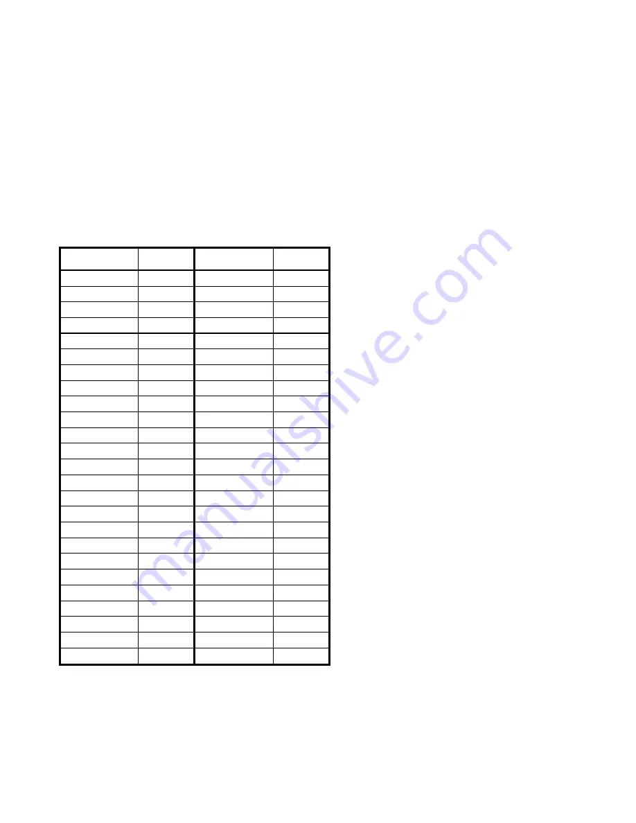
P1 of the IP module provides the logic interface to the mating connector
on the carrier board. This connector is a 50-pin female receptacle header
(AMP 173279-3 or equivalent) which mates to the male connector of the
carrier board (AMP 173280-3 or equivalent). This provides excellent
connection integrity and utilizes gold-plating in the mating area. Threaded
metric M2 screws and spacers are supplied with the IP module to provide
additional stability for harsh environments (see Drawing 4501-434 for
assembly details). Field and logic side connectors are keyed to avoid
incorrect assembly. The pin assignments of P1 are standard for all IP
modules according to the Industrial I/O Pack Specification (see Table 2.2).
Pin
Description
Pin
Number
Pin
Description
Pin
Number
GND
1
GND
26
CLK
2
+5V
27
Reset
#
3
R/W
#
28
D00
4
IDSEL
#
29
D01
5
DMAReq0
#
30
D02
6
MEMSEL
#
31
D03
7
DMAReq1
#
32
D04
8
IntSel
#
33
D05
9
DMAck0
#
34
D06
10
IOSEL
#
35
D07
11
RESERVED
3
36
D08
12
A1
37
D09
13
DMAEnd
#
38
D10
14
A2
39
D11
15
ERROR
3
40
D12
16
A3
41
D13
17
INTReq0
#
42
D14
18
A4
43
D15
19
INTReq1
#
44
BS0
#
20
A5
45
BS1
#
21
STROBE
#
46
-12V
2
22
A6
47
+12V
2
23
ACK
#
48
+5V
24
RESERVED
3
49
GND
25
GND
50
CONNECTORS
IP Logic Interface Connector
(P1)
Table 2.2:
Standard Logic
Interface Connections (P1)
1. # is used to indicate an
active-low signal.
2. Logic Lines are NOT
USED by this IP Model.
3. Logic Lines are reserved
for programming purposes.
(TMS#, TDO#, and TCLK)
Each has an active pull-up.

