SERIES IP503 INDUSTRIAL I/O PACK EIA/TIA-232E & CENTRONICS COMMUNICATION MODULE
___________________________________________________________________________________________
- 21 -
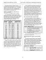
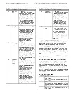
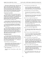
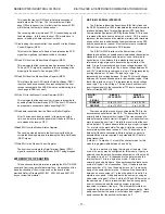
Data Register Buffers .................... The data registers are double-
buffered (16C450 mode), or
16-byte FIFO buffered (FIFO
mode)
Interrupts ....................................... Receiver Line Status Interrupt
(i.e. Overrun error, Parity
error, Framing error, or Break
Interrupt); Received Data
Available (FIFO level
reached) or Character time-
out; Transmitter Holding
Register Empty; or Modem
Status (CTS, DSR, RI, or
DCD)
DRIVERS:
Output Voltage Swing....................
±
10V Typical,
±
8V Minimum
(Loaded with 3K
Ω
to ground)
Output Short Circuit Current
±
........ 12mA Max,
±
6mA Min Output
Resistance300
Ω
Minimum
Propagation Delay (High-to-Low)... 2us Max (R
L
= 3K
Ω
, C
L
=
50pF)
Propagation Delay (Low-to-High)... 2us Max (R
L
= 3K
Ω
, C
L
=
50pF)
Output Slew Rate (+3V to -3V)4V/us Min to 30V/us Max (C
L
=
50-2500pF, R
L
= 3K
Ω
to 7K
Ω
)
RECEIVERS:
Input Voltage Range......................
±
25V DC Maximum
Input High Threshold ..................... 155V Minimum, 24V
Maximum
Input Low Threshold ...................... 065V Minimum, 135V
Maximum
Input Resistance............................ 3K
Ω
to 7K
Ω
Input Current ................................. 36mA to 83mA (V
IN
=
±
15V);
043mA to 1mA (V
IN
=
±
3V)
Rise Time ...................................... 175ns Maximum
Fall Time ....................................... 20ns Maximum
Propagation Delay (High-to-Low)... 50ns Maximum
Propagation Delay (Low-to-High)... 50ns Maximum
CENTRONICS PARALLEL PORT
Compatability. Centronics (completely compatible with the
parallel-port implementation used in the IBM serial/ parallel
adapter)
TerminationPD0-PD7, STB*, AFD*, INIT*, and SLIN*, are
terminated with 30
Ω
series resistors and 2200pF capacitors to
common; STB*, AFD*, INIT*, and SLIN* include 47K
Ω
pullups to
+5V
INDUSTRIAL I/O PACK COMPLIANCE
Specification. This module meets or exceeds all written Industrial
I/O Pack specifications per revision 071. Electrical/Mechanical
Interface. Single-Size IP Module
IP Data Transfer Cycle Types Supported:
Input/Output (IOSel*)D16 or D08 least significant
read/write of channel data
ID Read (IDSel*)32 x 8 ID PROM read on D0D7
Interrupt Select (INTSel*)8-bit word (D08) read of Scratch
Pad/Interrupt Vector Register
contents
Access Times (8MHz Clock):
ID PROM Read1 wait state (375ns cycle)
Channel Register R/W2 wait states (500ns cycle)
Interrupt Select Cycle Read2 wait states (500ns cycle)
APPENDIX
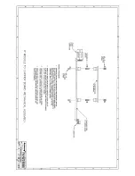
CABLE:MODEL 5025-550-x (Non-Shielded)
MODEL 5025-551-x (Shielded)
Type: Flat Ribbon Cable, 50-wires (female connectors at both
ends)The ‘-x’ suffix designates the length in feet (12 feet
maximum)Choose shielded or unshielded cable according to
model number. The unshielded cable is recommended for
digital I/O, while the shielded cable is recommended for
optimum performance with precision analog I/O applications
Application: Used to connect a Model 5025-552 termination
panel to the AVME9630/9660 non-intelligent carrier board A-
D connectors (both have 50-pin connectors)
Length: Last field of part number designates length in feet (user-
specified, 12 feet maximum)It is recommended that this
length be kept to a minimum to reduce noise and power loss
Cable:50-wire flat ribbon cable, 28 gage. Non-Shielded cable
model uses Acromag Part 2002-211 (3M Type C3365/50 or
equivalent)Shielded cable model uses Acromag Part 2002-
261 (3M Type 3476/50 or equivalent)
Headers (Both Ends):50-pin female header with strain relief
.
Header - Acromag Part 1004-512 (3M Type 3425-6600 or
equivalent)
Strain Relief - Acromag Part 1004-534 (3M Type
3448-3050 or equivalent)
Keying: Headers at both ends have polarizing key to prevent
improper installation
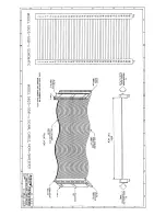
Schematic and Physical Attributes: For Non-Shielded cable
model, see Drawing 4501-462For Shielded cable model, see
Drawing 4501-463
Shipping Weight:10 pound (05Kg) packaged
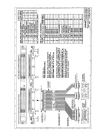
CABLE:MODEL 5029-944
Type: Model 5029-944 IP503 Communication Cable: A five foot
long, flat 50-pin cable with a female connector on one end
(for connection to AVME9630/9660 or other compatible
carrier boards) and two DE-9P connectors (serial ports) plus
one DB-25S connector (parallel port) on the other end
ApplicatIon: Used to connect to two DB-9 serial ports and 1
Centronics parallel port to AVME9630/9660 non-intelligent
carrier board A-D connectors. It is recommended for use
with Acromag Model IP503 serial communication modules
Length:5 feet
Cable: 50-wire flat ribbon cable, 28 gage. Non-Shielded cable
model uses Acromag Part 2002-211 (3M Type C3365/50 or
equivalent)
Headers:50-pin female header with strain relief
. Header -
Acromag Part 1004-512 (3M Type 3425-6600 or
equivalent)
Strain Relief - Acromag Part 1004-534 (3M Type
3448-3050 or equivalent)
Serial Port Connectors: Four DE-9P (9-pin, D-SUB, Male)
connectors with strain relief (3M connector U89809-9000 with
3448-8D09A strain relief, or equivalent)
Parallel Port Connector: One DB-25S (25-pin, D-SUB, Female)
connector (3M connector U89925-9000 with 3448-8D25A
strain relief, or equivalent)
Keying:50-pin Header at one end has polarizing key to prevent
improper installation
Schematic and Physical Attributes: See Drawing 4501-550
Shipping Weight:10 pound (05Kg) packaged


