Model TT235-0600
RTD/Resistance Thermometer Transmitter w/USB
Acromag, Inc. Tel: 248-295-0880
- 17 -
http://www.acromag.com
[
17
]
https://www.acromag.com
TECHNICAL REFERENCE
OPERATION STEP-BY-STEP
Connections
This section will walk you through
the Connection
–
Configuration
–
Calibration process step-by-step.
Before attempting to reconfigure or
recalibrate this transmitter, verify
the following electrical
connections:
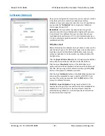
Calibration Connections:
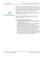
NOTE:
When calibrating, the input source, output meter, and load resistor (for
current output) must be accurate beyond the transmitter specifications, or better
than ±0.1%. As a general rule, calibration equipment accuracy should be four times
better than the rated accuracy you are trying to achieve with this transmitter.
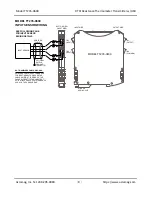
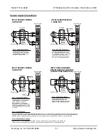
Connect Input:
Connect a precision resistance decade box to the input at TB1 and
TB2 according to the RTD configuration you will be using (Refer to Sensor Input
Connections). The resistance source must be adjustable over the range desired for
zero and full-scale. All input types share the same wiring and procedure for the
purpose of calibration.
Calibration & Configuration Connections:
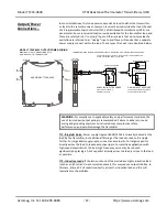
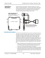
Connect Output/Power:
Refer to Output/Power Connection section and wire an
output current loop to the transmitter as illustrated. You will need to measure the
output current accurately in order to calibrate the transmitter. You can connect a
current meter in series in this loop to read the loop current directly (not
recommended). Alternatively, you could simply connect a voltmeter across a series
connected precision load resistor in the loop, and accurately read the output
current as a function of the IR voltage drop produced in this resistor
(recommended). In any case, be sure to power the loop with a voltage that is
minimally greater than the 11V required by the transmitter, plus the IR drop of the
wiring and terminals, plus the IR drop in the load. To computer the IR drop, be sure
to use a current level that considers the over-scale current (up to 24mA).
Loop Power Supply Voltage:
Make sure your voltage level is at least 11V plus
0.020*load_resistance. Ideally, it should be great enough to drive the 24mA over-
range current into your load (i.e. up to 11V+ 0.024*Rload, assuming line drop is
negligible and the maximum possible over-range is considered). Always apply
power to the transmitter output loop even when connected to USB.
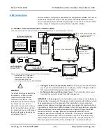
Connect to PC via USB:
Refer to USB Connections section and connect the
transmitter to the PC using the USB isolator and cables provided in the
Configuration Kit TT-SIP.
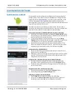
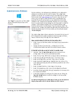
Now that you have made your connections and applied power to your loop, you
can execute the
“
TT235 Config.exe
”
software to begin configuration of the
transmitter (software is compatible with XP or later versions of the Windows
operating system).
Connect Input
Connect
Output/Power
Connect PC/USB
Configure
Optional
Calibrate I/O

