Model TT235-0600
RTD/Resistance Thermometer Transmitter w/USB
Acromag, Inc. Tel: 248-295-0880
- 24 -
http://www.acromag.com
[
24
]
https://www.acromag.com
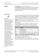
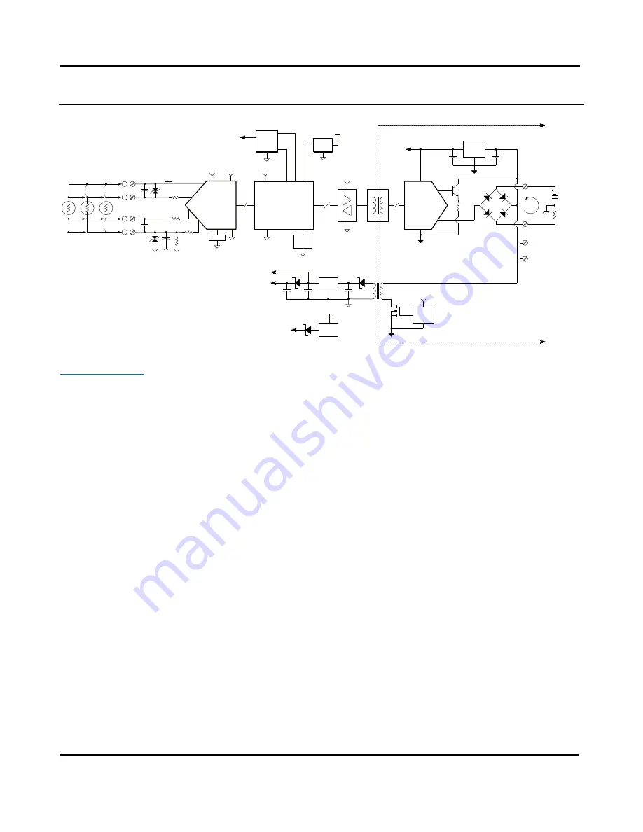
BLOCK DIAGRAM
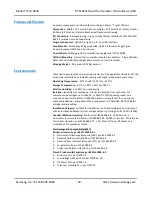
How It Works
Key Points of Operation
Loop Powered
Input is Isolated from
Output
Input circuit is common to
USB ground
USB powers a portion of
the input circuit when
connected, but not the
output
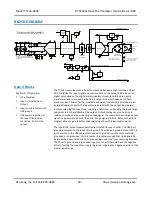
The TT235 transmitter uses a 32-bit microcontroller and a high-resolution 24-bit
ADC to digitize the input signal and communicate to the output DAC via a serial
digital pulse stream. The digital communication stream is isolated via a pulse
transformer and is received by the 16-bit output DAC which drives a 4
–
20mA
process current. Power for the isolated input side of the circuit is provided via an
isolated flyback converter that operates in parallel with the output loop. Setup
involves selecting the input type, selecting a filter level, and scaling the input range
endpoints to 4mA and 20mA at the output. Output scaling can also be done in
reverse to produce a reverse acting output signal. The maximum over-range output
signal is approximately 24mA, the under-range signal is 3.5mA. Refer to the block
diagram above to gain a better understanding of how this transmitter works.
The input/USB, output/power circuits are isolated from each other. The USB port
ground is common to the input circuit ground. The USB port ground of most PC’s is
also common to the USB cable shield and earth ground. Input sensors could be
grounded or ungrounded. For this reason, it is recommended that USB signals be
isolated when connected to a PC to prevent a ground loop from occurring between
the PC earth ground and a grounded input sensor, which would have the negative
affect of pulling the input bias supply to ground, clipping the negative portion of the
bipolar input range.
TT235-0600 SIMPLIFIED SCHEMATIC
(FILTERING AND DETAIL OMITTED FOR CLARITY)
3.3V
24b A/D CONV
R
12-36VDC
+
-
~
~
20
LDO
REG
16-BIT DAC
+
-
LOOP+
LOOP-
4-20
mA
ISOLATED OUTPUT
MICROCONTROLLER
+3.3V
LDO
3.XV
USB
3.3V
OSC
3.3V
TWO-WIRE OUTPUT
PORT
POLARITY
PROTECTION
ISOLATED FLYBACK CONVERTER
TRI-STATE
BUFFERS
3.XV
1
2
I
LOAD
EARTH
GROUND
ISOLATED OUTPUT
12-36V
TB3
C
C 2
1
TB4
THERE ARE NO INTERNAL
C CONNECTIONS ARE USED
FOR OPTIONAL SOURCED
WIRING CONNECTIONS
CONNECTIONS TO C TERMINALS
3.XV
3.XV
RST
GEN
3.3V
USB
V-MON
5V
5V
1.25V
Vref
+3.4V
LDO
3.XV
5V
3
2
TB1
1
4
TB2
1K
–
L
+
H
I = 1mA
499
4-WIRE
3-WIRE
2-WIRE
1K
1K
TB2
2-WIRE & 3-WIRE CONFIGURATIONS
REQUIRE JUMPER CONNECTIONS AS
INDICATED.
JU
M
P
E
R
JU
M
P
E
R
JU
M
P
E
R
6
5
8
7


