VPX4812A/4814A
User’s Manual
Single-Slot 3U VPX Bus XMC Carrier Card/Switch Card Module
Acromag, Inc. Tel: 248-295-0310 - 17 - www.acromag.com
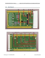
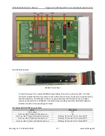
Front Panel Layout
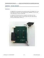
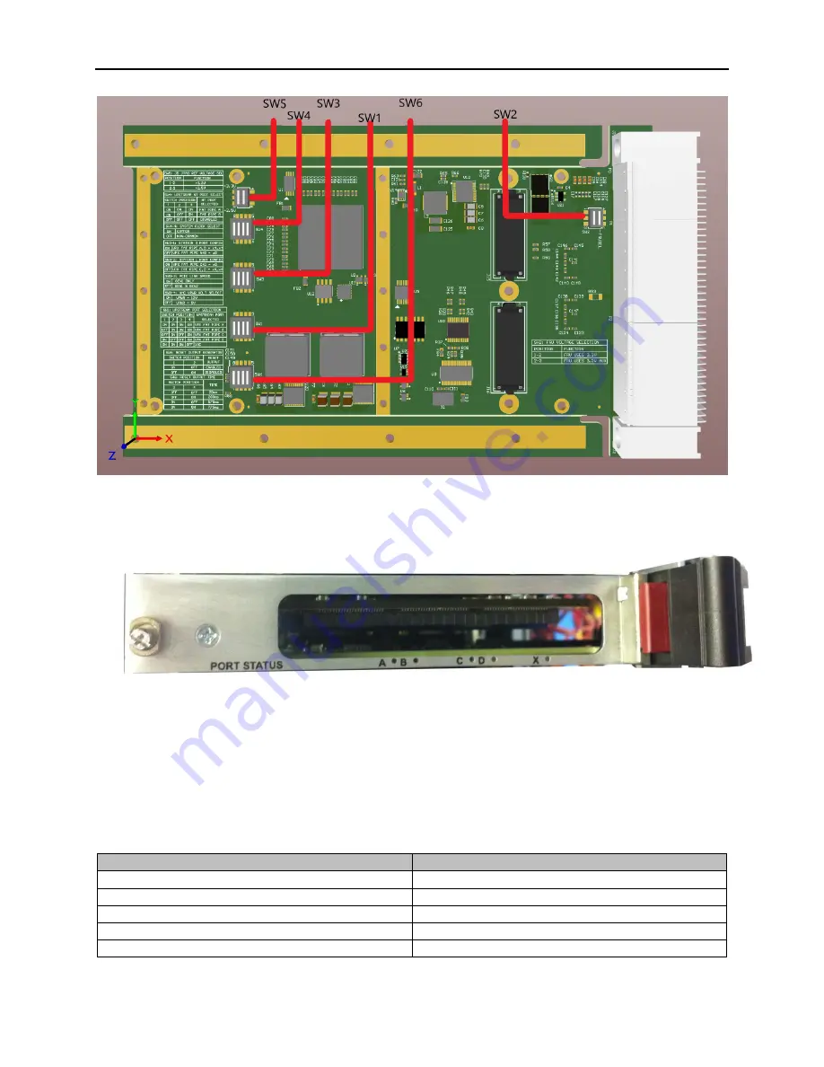
VPX4812A Front Panel
On the front panel of air-cooled VPX4812A
assemblies, there are 5 port status LED’s. The first
four LED’s indicate the PCIe link status for each of the four Fat Pipe connections
to other slots on
the VPX backplane. The fifth LED on the front panel indicates the PCIe link status of an XMC
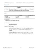
module connected to the VPX4812A. The table below describes what the LED On/Off patterns
indicate about the corresponding port states.
Port Status LED On/Off Patterns, by State
State
LED Pattern
Link is down
Off
Link is up, Gen 2.0 speed, all Lanes are up
On
Link is up, Gen 2.0 speed, reduced Lanes are up
Blinking, 0.5 seconds On, 0.5 seconds Off
Link is up, Gen 1.0 speed, all Lanes are up
Blinking, 1.5 seconds On, 0.5 seconds Off
Link is up, Gen 1.0 speed, reduced Lanes are up
Blinking, 0.5 seconds On, 1.5 seconds Off

