background image

VPX4812A/4814A 

User’s Manual


Single-Slot 3U VPX Bus XMC Carrier Card/Switch Card Module 

Acromag, Inc. Tel: 248-295-0310                                                    - 18 -                                                www.acromag.com 

8.0 


Handling 


Modules should be handled in ESD-safe work areas in order to 
prevent damage to sensitive components from electrostatic 
discharges. These areas must be designed and maintained to prevent 
ESD damage. 

 
ESD Safe Work Area Guidelines 


1.


Module should be handled at properly designated work areas 
only. 
 

2.


Designated ESD safe work areas must be checked periodically to 
ensure their continued safety from ESD. The areas should be 
monitored for the following: 

a.


Proper grounding methods. 

b.


Static dissipation of work surfaces. 

c.


Static dissipation of floor surfaces. 

d.


Operation of ion blowers and ion air guns. 
 

3.


Designated work areas must be kept free of static generating 
materials such as Styrofoam, vinyl, plastic, fabrics, or any other 
static generating materials. 
 

4.


Work areas must be kept clean and neat in order to prevent 
contamination of the work area. 


5.


Modules should be handled by the edges. Avoid touching 
component leads. 
 

NOTE:


When not installed in a system, modules must be enclosed 

in shielded bags or boxes. There are three types of ESD protective 
enclosure materials this module was shipped in an approved ESD 
bag. 
 

6.


Whenever handling the module, the operator must be properly 
grounded by one of the following: 

a.


Wearing a wrist strap connected to earth ground. 

b.


Wearing heel grounders and have both feet on a static 
dissipative floor surface. 
 

7.


Stacking of modules should be avoided to prevent physical 
damage. 


Summary of Contents for VPX4812A

Page 1: ...pport VPX Switch Card USER S MANUAL ACROMAG INCORPORATED 30765 South Wixom Road Wixom MI 48393 2417 U S A Tel 248 295 0310 Email solutions acromag com Copyright 2020 Acromag Inc Printed in the USA Dat...

Page 2: ...this manual and makes no commitment to update or keep current the information contained in this manual No part of this manual may be copied or reproduced in any form without the prior written consent...

Page 3: ...Operational Block Diagram 10 5 0 Board Layout 11 6 0 Connectors 12 P0 Connector 12 P1 Connector 12 P2 Connector 13 J15 Connector 13 J16 Connector 14 J5 Connector JTAG Header 14 7 0 Switch Settings 15...

Page 4: ...nc Tel 248 295 0310 4 www acromag com Environmental 22 EMI EMC Regulatory Compliance 23 11 0 Service and Repair 24 Service and Repair Assistance 24 Preliminary Service Procedure 24 Where to Get Help 2...

Page 5: ...ons or a single Double Fat Pipe connection The VPX4812A also provides support for a VPX Double Fat Pipe x8 connection to an XMC card at Gen 2 0 speeds The VPX4814A disconnects the PCIe connection on t...

Page 6: ...eeds When utilizing the VPX4812A as a switch card a CPU module configured to be an upstream port can communicate with up to three downstream VPX cards in the system as well as an XMC module on the 481...

Page 7: ...wider range of OpenVPX backplane profiles including profiles that contain Ethernet control plane interfaces on P1 Build Levels The VPX4812A 14A is available in three electrically compatible build leve...

Page 8: ...0310 8 www acromag com 2 0 Ordering Information Available Models VPX4812A LF VPX4812A Air cooled Model VPX4812A CC LF VPX4812A Conduction cooled Model VPX4812A REDI LF VPX4812A REDI Model VPX4814A LF...

Page 9: ...suggested that salvageable shipping cartons and packing material be saved for future use in the event the product must be shipped This board is physically protected with packing material and electrica...

Page 10: ...VPX4812A 4814A User s Manual Single Slot 3U VPX Bus XMC Carrier Card Switch Card Module Acromag Inc Tel 248 295 0310 10 www acromag com 4 0 Operational Block Diagram...

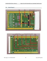
Page 11: ...VPX4812A 4814A User s Manual Single Slot 3U VPX Bus XMC Carrier Card Switch Card Module Acromag Inc Tel 248 295 0310 11 www acromag com 5 0 Board Layout...

Page 12: ...NC 6 GND PCIE_VPX_P5_RXP PCIE_VPX_P5_RXN GND PCIE_VPX_P5_TXP PCIE_VPX_P5_TXN GND 7 PCIE_VPX_P6_RXP PCIE_VPX_P6_RXN GND PCIE_VPX_P6_TXP PCIE_VPX_P6_TXN GND NC 8 GND PCIE_VPX_P7_RXP PCIE_VPX_P7_RXN GND...

Page 13: ...D J16_DP14_N J16_DP14_P GND 15 J16_DP17_N J16_DP17_P GND J16_DP16_N J16_DP16_P GND NC 16 GND J16_DP19_N J16_DP19_P GND J16_DP18_N J16_DP18_P GND J15 Connector A B C D E F 1 PCIE_XMC_P0_RXP PCIE_XMC_P0...

Page 14: ...J16_SIO10_P J16_DP09_P J16_DP09_N J16_SIO11_P 10 GND GND J16_SIO8_N GND GND J16_SIO9_N 11 J16_DP10_P J16_DP10_N J16_SIO8_P J16_DP11_P J16_DP11_N J16_SIO9_P 12 GND GND J16_SIO6_N GND GND J16_SIO7_N 13...

Page 15: ...ON ON VPX Fat Pipe B OFF ON OFF ON VPX Fat Pipe C ON OFF OFF ON VPX Fat Pipe D ON ON ON OFF XMC SW2 FRUSEL 1 2 default FRU uses 3 3V 2 3 FRU uses 3 3V_AUX 4 5 Unused 5 6 Unused SW3 1 STATION 0 PORT CO...

Page 16: ...lock generated on board for PCIe timing Note Best system stability may be achieved with the use of a 100MHz common clock connection from the SBC especially at Gen 2 0 link speeds If the system does no...

Page 17: ...ne The fifth LED on the front panel indicates the PCIe link status of an XMC module connected to the VPX4812A The table below describes what the LED On Off patterns indicate about the corresponding po...

Page 18: ...ation of floor surfaces d Operation of ion blowers and ion air guns 3 Designated work areas must be kept free of static generating materials such as Styrofoam vinyl plastic fabrics or any other static...

Page 19: ...e pins are keyed to prevent cards from being inserted into incorrect backplane slot s to avoid electrical incompatibility The VPX4812A has receptacles for these guide pins see the Connectors section B...

Page 20: ...VITA 65 0 2019 which states that Plug In Modules should only use VS1 12V 3 3V_AUX and VBAT as power inputs from the backplane and derive all other voltage rails from that The VPX4812A VPX4814A does n...

Page 21: ...ltages on the board Once all of the on board regulators outputs are stable and the backplane SYSRST signal is de asserted the on board circuitry will be taken out of reset The VPX4812A VPX4814A contai...

Page 22: ...e in a fully installed conduction cooled rack 2 must operate in a fully installed conduction cooled REDI rack Relative Humidity 5 to 95 non condensing Vibration and Shock Standards Vibration Random Op...

Page 23: ...ive 2004 108 EC Immunity per EN 61000 6 2 Electrostatic Discharge Immunity ESD per IEC 61000 4 2 Radiated Field Immunity RFI per IEC 61000 4 3 Electrical Fast Transient Immunity EFT per IEC 61000 4 4...

Page 24: ...refer to the documentation for the XMC module to verify that it is correctly configured Replacement of the module with one that is known to work correctly is a good technique to isolate a faulty modu...

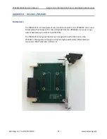
Page 25: ...is a development rear transition module for the VPX4812A and is used in backplanes that bring out the rear I O signals from the VPX4812A If you are using a custom backplane you will not need the RTM T...

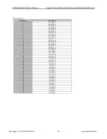
Page 26: ...ND 13 J16_SIO3_P J16_SIO3_N GND J16_SIO2_P Unused GND Unused 14 GND J16_SIO1_P J16_SIO1_N GND Unused Unused GND 15 J16_DP01_N J16_DP01_P GND J16_DP00_N Unused GND Unused 16 GND J16_DP03_N J16_DP03_P G...

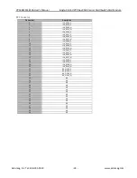
Page 27: ...8 J16_DPO11_N 9 J16_DPO2_P 10 J16_DPO12_P 11 J16_DPO2_N 12 J16_DPO12_N 13 J16_DPO3_P 14 J16_DPO13_P 15 J16_DPO3_N 16 J16_DPO13_N 17 J16_DPO8_P 18 J16_DPO9_P 19 J16_DPO8_N 20 J16_DPO9_N 21 J16_SIO0_P 2...

Page 28: ...J16_DP04_N 4 J16_DP14_N 5 J16_DP05_P 6 J16_DP15_P 7 J16_DP05_N 8 J16_DP15_N 9 J16_DP06_P 10 J16_DP16_P 11 J16_DP06_N 12 J16_DP16_N 13 J16_DP07_P 14 J16_DP17_P 15 J16_DP07_N 16 J16_DP17_N 17 J16_DP18_...

Page 29: ...ined when power is removed Yes No Type EEPROM Flash etc EEPROM AT25640B Size 64 KB User Modifiable Yes No Function Store settings for PEX8624 PCIe switch Process to Sanitize Device can be accessed via...

Page 30: ...rrier Card Switch Card Module Acromag Inc Tel 248 295 0310 30 www acromag com Revision History The following table shows the revision history for this document Release Date Version EGR DOC Description...

Reviews: