VPX4812A/4814A
User’s Manual
Single-Slot 3U VPX Bus XMC Carrier Card/Switch Card Module
Acromag, Inc. Tel: 248-295-0310 - 21 - www.acromag.com
Caution
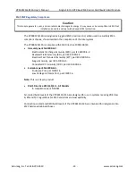
If VPWR is set to 12V, you must ensure that the XMC card is capable of handling a 12V supply voltage. If the XMC
card is not capable of handling a 12V supply voltage, ensure that the VPWR switch is set to supply 5V.
Auxiliary Supply
The following functions may be powered from the 3.3V Auxiliary supply (VPX +3.3V_AUX line):
FRU EEPROM
TEMP SENSOR
Power-Up/Reset Sequence
Upon the +12V (VS1) rail reaching 90% (10.8V), the on-board regulators are enabled to generate the
required voltages on the board. Once all of the on-
board regulators’ outputs are stable and the
backplane SYSRST# signal is de-asserted, the on-board circuitry will be taken out of reset.
The VPX4812A/VPX4814A contains an optional, configurable power-up reset delay circuit. If enabled,
the circuit will assert the backplane SYSRST# signal for a configurable length of time determined by the
configuration of SW6. This is intended to be used in situations where a device in the system requires
longer than the 100ms requirement of the PCI Express specification to load and configure itself for
enumeration.
Bus Compliance
VITA 46.0, 46.4, 46.9, 48 and 65
MIL Spec 217-F MTBF
–
TBD
Form Factor
3U VPXbus 3.94” (100mm) x 6.3” (160mm)
Flammability
The circuit board is made by an UL recognized manufacturer and has a flammability rating of
UL94V-1.


