BusWorks Model XT1533-000
4 CH Current 4 CH Digital I/O w/USB & Profinet
Acromag, Inc. Tel: 248-295-0880
- 18 -
http://www.acromag.com
- 18 -
http://www.acromag.com
TECHNICAL REFERENCE
CONFIGURATION STEP-BY-STEP
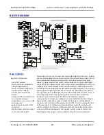
Getting Connected
This section will walk you through
the Connection-Configuration
process step-by-step. But before
you attempt to reconfigure this
module, please make the following
electrical connections.
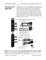
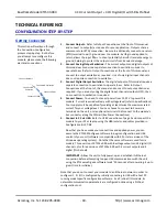
1. Connect Outputs:
Refer to Output Connections at the front of this manual
and connect to output(s) as required for your application. Outputs share a
common return (RTN) connection. Be sure to additionally connect one return
(RTN) terminal to earth ground near the module. Earth ground applied to
return allows the input filters to shunt potentially harmful transient energy to
ground, helping to protect the output circuits from transient damage.
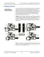
2. Connect Analog Output Excitation:
The current outputs and digital outputs of
this model each require a separate connection to excitation in order to
operate them. Refer to Output Connections at the front of this manual and
connect to output excitation as required. Use of only digital input channels
does not require connection to excitation.
3. Connect Digital Output Excitation:
The digital outputs of this model require a
separate connection to excitation to operate them. Refer to Output
Connections at the front of this manual and connect to output excitation as
required. If you are only using the digital input channels (outputs OFF), then
no connection to excitation is required.
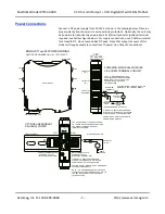
4. Connect Power:
You need to connect power from 12-32V to power this
module. Current required will vary with voltage level (refer to Specifications).
Your supply must be capable of providing at least twice the maximum rated
current for your voltage level. You can choose to connect to Power via
terminals on the unit, or via optional terminals that conne
ct to the module’s
bus connector along the DIN rail (See Power Connections).
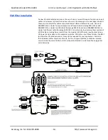
5. Connect to PC via USB:
Refer to USB Connections of page 9 and connect the
module to your PC or laptop using the USB isolator and cables provided in
Configuration Kit XT-SIP.
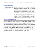
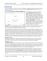
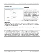
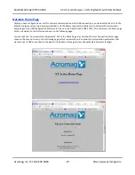
Now that you have made your connections and applied power, you can
execute the XT15XXConfig.exe software to begin configuration and USB
control of your unit (software is compatible with XP or later versions of the
Windows operating system). Note that the same software is used for six
models, Three version of XT154x-000 with 8 voltage outputs and 4 digital I/O
channels, plus three versions of XT153x-000 with 4 current outputs and 4
digital I/O channels.
IMPORTANT:
Allow the unit to fully power-up and establish its Ethernet
connection before attempting to open USB communications with the unit
using the XT15xxconfig.exe software (wait ~30 seconds after powering-it up to
give it time to initialize).
Note that you do not connect your module to an Ethernet network in order to
configure it. Its I/O is configured by initially connecting to USB with a host PC
running model-specific configuration software. As a Profinet I/O module, its
network communication parameters are configured online using a Profinet
configuration tool.
Connect Outputs
Connect AO Excitation
Connect DO
Excitation
Connect Power
Connect PC/USB
Configure


