BusWorks Model XT1533-000
4 CH Current 4 CH Digital I/O w/USB & Profinet
Acromag, Inc. Tel: 248-295-0880
- 22 -
http://www.acromag.com
- 22 -
http://www.acromag.com
I/O Config/Test Page
You can click the
“I/O Config/Test Page”
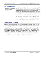
page tab to begin configuring the unit, and/or optionally test its operation. The
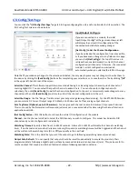
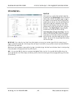
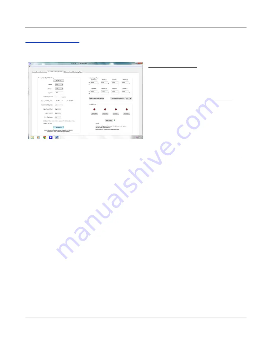
I/O Config/Test screen is shown below:
Input/Output Configure
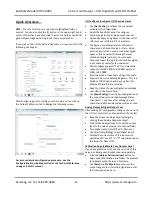
If you are connected to a module, the initial
Input/Output Config/Test Page screen shown at left
will display the current I/O configuration of the
connected module before making changes.
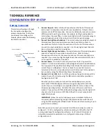
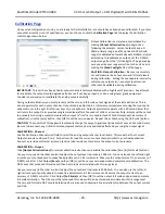
[Get Config] to Get the Channel Configuration
…
If you have loaded the configuration from a saved file,
or if you have made changes to any fields on this page,
you can click
[Get Config]
at the top of the screen to
retrieve the connected module’s current I/O channel
configuration (all channels). Otherwise, the connected
module’s current configuration was loaded
automatically when you selected the tab for this page.
Note that if you make any changes to the selections indicated, the only way to preserve your changes is to write them to
the device by clicking the
[Send Config]
button after completing your selections, or to save them to a file by clicking
“
F
ile”
in the upper left-hand corner of the screen.
Select the Channel:
This software supports two core models having 4 or 8 analog output channels, plus 4 channels of
sourcing digital I/O. You can select the specific channel to address here. You can choose to configure channel’s
selectively, then click
[Send Config]
to write the channel configuration to the unit, or more simply make changes to many
channels and then click
[Send Config]
one time to write all the channel configurations to the unit.
Select the Range:
Use the “Range:” field to select your output range (analog channels only). For the
XT1533-000 model,
you can select a DC Current Output range of 0-20mA or 4-20mA at each of four analog output channels.
Set a Tag Name (Optional, up to 8 Characters):
You can give each channel a name to document its purpose if desired.
This is not used by the firmware or software and just serves as a convenient label for discerning the channel function or
application over USB.
[Get Config] Button:
Click this button to retrieve the entire I/O configuration of the module.
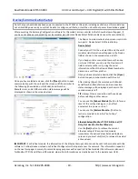
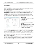
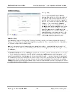
Channel:
Use the channel scroll bar to select the DIO channel you wish to configure. This model has 4 discrete DIO
channels and you can configure each individually.
Watchdog Timeout:
Specify a time from 1 to 65534 seconds. A time of 0 or 65535 will disable the channel’s watchdog
timer. If no channel read or write activity occurs during this period, a watchdog timeout will be triggered and the channel
will be written to the watchdog state (On or Off) you specify in the next field.
Watchdog State:
This is the state that you want the output to go to following a watchdog timeout (see above).
Output Auto-Refresh:
You can specify that outputs should be rewritten periodically to ensure they maintain their
programmed state following a digital upset, perhaps by some extraordinary transient event (rare). This is also useful to
reset an output that may be in a latched thermal shutdown following overload conditions.


