BusWorks Model XT1533-000
4 CH Current 4 CH Digital I/O w/USB & Profinet
Acromag, Inc. Tel: 248-295-0880
- 25 -
http://www.acromag.com
- 25 -
http://www.acromag.com
Calibration Page
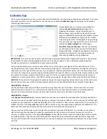
Once you’ve configured your unit, you are ready for field installation, as outputs have already been calibrated. If you late
r
encounter error that is out of specification, you can choose to click the
Calibration Page
tab to display the Calibration
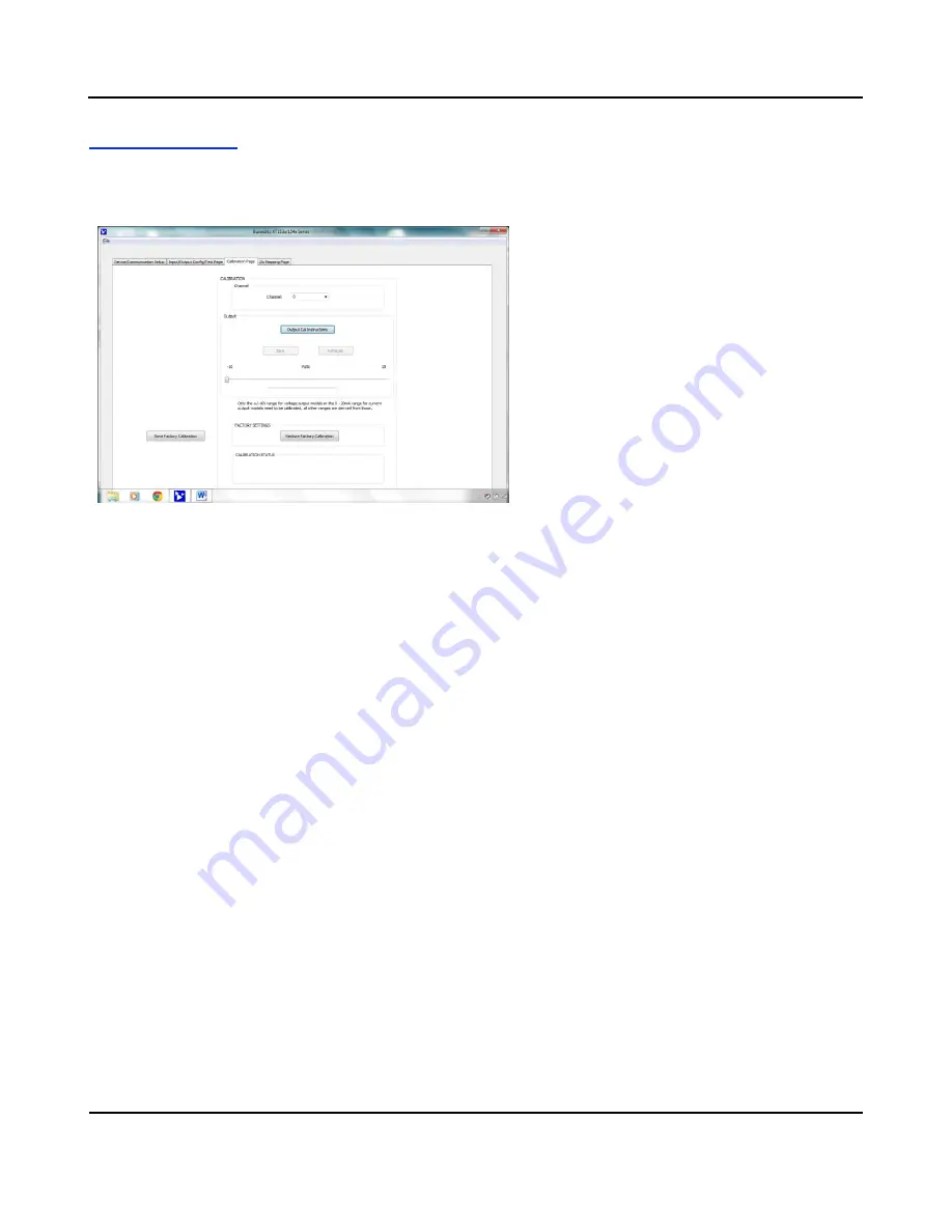
control page shown below:
Output Calibration is a simple process initiated by
clicking
[Output Cal Instructions]
to begin, then
following the prompts. Current outputs have a 0-
20mA primary range, and the optional 4-20mA sub-
range is calibrated automatically with 0-20mA. Before
attempting to recalibrate an output, set the 0-20mA
output range from the “I/O Config/Test” page, making
sure you write your range selection to the unit by also
clicking the
[Send Config]
button of that page.
CAUTION - Output Calibration:
Be sure to accurately
set and measure the output zero and full-scale levels
during calibration. Setting these endpoints incorrectly
will produce output error, as output levels cannot
otherwise be validated during calibration.
IMPORTANT:
This unit has already had its output channels factory calibrated with a high level of precision. Any attempt
to recalibrate the outputs could degrade performance if not done properly, or done using lower grade equipment.
Consider your decision to recalibrate the analog outputs carefully.
During output calibration, you must precisely set the zero and full-scale output signals at the selected channel. This is
done separately for each output channel. Outputs can be adjusted in 1 lsb increments/decrements using the mouse and
slide control, and the right & left arrow keys of your keyboard. Output adjustments operate with a 30 second timer that
will return the output to its previous programmed level after 30 seconds of slide or arrow inactivity. Simply set the output
to precisely 1mA using a meter to measure the output
(a “live” zero is used instead of 0mA to improve the accuracy of
calibration), click the [zero] button, then [OK] to set the zero endpoint. Repeat this at 20mA using the [full-scale] button.
CAUTION:
The controls of this page will temporarily change the output signal level (slide control uses a 30 second timer).
Be sure to disconnect any critical control equipment that may be inadvertently affected by varying the output signal.
CALIBRATION
–
Channel
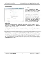
Use the Calibration Channel scroll field to select the analog output channel to calibrate. This model has four Current
Output channels numbered 0 to 3. For best results, load the current output channel similar to your final application.
Connect a precision voltmeter across a precision load resistance to measure the output current precisely.
CALIBRATION
–
Output
Click
[Output Cal Instructions]
to receive calibration instructions and enable the calibration [Zero] & [Full-Scale] buttons.
Use your mouse and the slider control to adjust the output level to precisely 1.000mA. You can also use the left and right
arrow keys of your keyboard to make fine adjustments in 1 lsb increments. Measure the output current to an accuracy of
0.025% or better. Click Output
[Zero]
and then [OK] to set the output zero endpoint and complete zero calibration. The
DAC count that produced this value will then be stored and associated with this range level.
Use your mouse and the slider control to adjust the output level to precisely 20.000mA. You can also use the left and
right arrow keys of your keyboard to make fine adjustments in 1 lsb increments. Measure the output current to an
accuracy of 0.025% or better. Click Output
[Full-Scale]
and then [OK] to set the output full-scale endpoint and complete
full-scale calibration. The DAC count that produced this value will then be stored and associated with this range level.
The zero and full-scale DAC counts determined here are used to develop a linear relationship between the output current
and DAC.

