ACM-XD15B7
10
Acrosser Technology Co., Ltd.
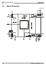
2.2. Connector Pin Definition
CPU
Intel Xeon D Processor (Industrial grade)
Xeon
®
D1548 2.0/2.6GHz 12MB Cache, 45W (8 core )
FCBGA1667 37.5x37.5mm
DIMM1/DIMM2
CN_DIMM_1&2 DDR4 SO-DIMM 260P
CPUFAN1
3-pin Fan Connector
Pin # Signal
1
GND
2
+12V
3
FAN Speed Sensor
Header: 3-pin. Pitch: 2.54mm.
CPLD
CPLD Power Manager
CN1
COM-Express 220Pin male H3.25mm Pitch:0.5mm TYPE 7 C&D
CN2
COM-Express 220Pin male H3.25mm Pitch:0.5mm TYPE 7 A&B
SPI_ROM
For BIOS Firmware SPI_128Mb
2.2.1.
CN1, CN2 Pin Assignments
This module is connected to the carrier board via two 220-pin connectors for a total
of 440 pins connectivity. These connectors are broken down into four rows. The CN2
connector consists of rows A and B, while the CN1 connector consists of rows C and
D.
Pin #
CN2 – Row A
CN2 – Row B
CN1 – Row C
CN1 – Row D
1
GND (FIXED)
GND (FIXED)
GND (FIXED)
GND (FIXED)
2
GBE0_MDI3-
GBE0_ACT#
GND (FIXED)
GND (FIXED)
3
GB
LPC_FRAME#
USB_SSRX0-
USB_SSTX0-
4
GBE0_LINK100#
LPC_AD0
US
US
5
GBE0_LINK1000#
LPC_AD1
GND (FIXED)
GND (FIXED)
6
GBE0_MDI2-
LPC_AD2
USB_SSRX1-
USB_SSTX1-
7
GB
LPC_AD3
US
US
8
No Connect
LPC_DRQ0#
GND (FIXED)
GND (FIXED)
9
GBE0_MDI1-
LPC_DRQ1#
USB_SSRX2-
USB_SSTX2-


