background image


75

Summary of Contents for AIV-HM76V0FL Series

Page 1: ...AIV HM76V0FL User Manual 1 ...

Page 2: ...amages This document contains proprietary information protected by copyright All rights are reserved No part of this Manual may be reproduced by any mechanical electronic or other means in any form without prior written permission of the manufacturer Trademarks AIV HM76V0FL are registered trademarks of Acrosser IBM PC is a registered trademark of the International Business Machines Corporation Pen...

Page 3: ...H W Information 24 4 1 24 Mainboard illustration Top Side 4 2 25 Locations of IO ports Jumper settings definition Chapter 5 BIOS Settings 35 5 1 36 Main Setup 5 2 39 Advanced Chipset Setup 5 3 48 Chipset Setup 5 4 53 Boot Setup 5 5 54 Security setup 5 6 55 Save Exit Setup Chapter 6 Function Description 57 6 1 57 Power input connection 6 2 57 Digital Inputs 6 3 59 Digital Outputs 6 4 60 Watchdog Ti...

Page 4: ...lation and Programming Guide 84 8 1 84 CAN bus 8 2 85 CAN Message Format 8 3 87 GPIO and Watchdog 8 4 88 Power Subsystem 8 5 89 I Button Function 8 6 90 API List and Descriptions Appendix A 106 Appendix B GPIO cable color 107 4 ...

Page 5: ...ligent power management function with software utility to monitor power status and control power sequence and also compliant with most industry standards for in vehicle usage including CE FCC and E Mark 1 1 Specifications Support Intel 3rd generation Core i3 i5 i7 CPU HM76 chipset DDR3 SO DIMM 2 up to16GB memory Display VGA HDMI DVI Combo connector VGA Audio USB DC power SATA x 2 SATA power x 2 Sw...

Page 6: ...are Fuse 10A x 1 SATA SATA power cable x 1 Remote Switch Cable x 1 GPIO CAN Driver ID DB15 Connector x 1 1 3 Features Rugged fanless design Support Intel 3rd generation Core i3 i5 i7 CPU HM76 chipset 2 DDR3 SO DIMM up to 16GB Support CAN 2 0A 2 0B protocol and I Button for driver ID VGA HDMI DVI I output Variety Wireless Communication Combo connector to simplify touch monitor installation 6 ...

Page 7: ...1 4 System Dissection 1 4 1 Dimensions 7 ...

Page 8: ...1 4 2 I O Panel FRONT IO PRINT Rear I O PRINT 8 ...

Page 9: ...uration 8 6 7 5 4 2 1 3 Item Description Quantity 1 DDR3 module 1 2 GPS Bluetooth module 1 3 AIV HM76V0FL main board 1 4 Module Heat Spreader 1 5 SIM card connector 1 6 Wi Fi 3 5G module 1 7 CF Bracket 1 8 HDD Bracket 1 9 ...

Page 10: ...Chapter 2 Procedures of Assembly Disassembly 2 1 2 5 HDD Installation The following instructions will guide you to install HDD step by step 2 1 1 Unfasten the screw of chassis UNSCREW 10 ...

Page 11: ...2 1 2 Open the bracket Assemble HDD into bracket by fastening 4 screws 11 ...

Page 12: ...12 ...

Page 13: ...2 1 3 Assemble the HDD bracket back to system Finish SCREW 13 ...

Page 14: ...2 2 CF Card Installation 2 2 1 Unfasten the 2 screws and pull the CF bracket from I O panel 14 ...

Page 15: ...2 2 2 Assemble the CF card with CF bracket The direction for installing the CF card 15 ...

Page 16: ...Finish 16 ...

Page 17: ...2 3 SIM Card Installation 2 3 1 Unfasten the 3 screws from Rear I O panel 17 ...

Page 18: ...2 3 2 Insert SIM card Step1 Step2 18 ...

Page 19: ...Finish 19 ...

Page 20: ...2 4 Antenna Installation Tack out antenna from packing bag and install 20 ...

Page 21: ...Board Guide 21 ...

Page 22: ...n with software utility to monitor power status and control power sequence and also compliant with most industry standards for in vehicle usage including CE FCC and E Mark 3 1 Specifications Support Intel 3rd generation Core i3 i5 i7 processor CPU HM76 chipset DDR3 SO DIMM 2 up to 16GB memory Display VGA HDMI DVI Combo connector VGA Audio USB DC power SATA x 2 SATA power x 2 Swappable Anti Shock 2...

Page 23: ...3 2 Package Contents Check if the following items are included in the package Quick Manual AIV HM76V0 board 1 x Software Utility CD 3 3 Block Diagram 23 ...

Page 24: ... the unpacking information which you should read carefully as well as the jumper switch settings for the AIV HM76V0 configuration 4 1 Mainboard illustration Top Side MINIPCIE1 Mini PCI Express Slot1 rPGA988B CPU Socket MINIPCIE2 Mini PCI Express Slot2 DIMM1 204 Pin DDR3 Socket Intel HM76 PCH DIMM2 204 Pin DDR3 Socket RTC1 System RTC battery socket 1 7 6 2 3 5 4 24 ...

Page 25: ...4 2 Locations of IO ports Jumper settings definition TOP SIDE 23 24 25 26 5 6 12 11 7 10 9 8 17 16 15 14 13 22 21 20 19 18 2 3 4 1 25 ...

Page 26: ...Bottom SIDE 27 26 ...

Page 27: ...ctor Include GPIO CANBUS I Button Signal SW3 For RS 422 RS 485 function select COM2_485 Pin Header for COM2 use RS 422 485 function SW2 For RS 422 RS 485 function select COM2 Pin Header for COM2 use RS 232 function SATA2 SATA device connector 2 COM1 Pin Header for COM1 use RS 232 function SATA1 SATA device connector 1 AUDIO1 AUDIO connector BT1 For Bluetooth Modular Connector CN1 RJ45 USB 2 ports ...

Page 28: ...C3 4 VCC5 SATA_PWR2 SATA Device Power Connector PIN SIGNAL 1 12V 2 GND 3 VCC3 4 VCC5 5 COMBO1 COMBO Connector 6 GPIO1 GPIO Connector PIN SIGNAL PIN SIGNAL 1 US 11 DD B CCL 2 US 12 VC B C12 3 GN 13 GN D D 4 VC 14 u C5 A do_R 5 GN 15 GN D D 6 RE 16 NC D 7 Gr 17 u een A do_L 8 Blu 18 NC e 9 HS NC YNC 19 10 D VSYNC 20 D CDA GPIO Pin Define PIN INE INE DEF PIN DEF 1 PO0 O1 G 2 GP 3 PO2 O3 G 4 GP 5 ND G...

Page 29: ...2 6 NA 7 422_RX2 8 NA 9 422_485_SEL_L 10 GND COM2 For RS 232 Function Pin SIGNAL 1 DSR 2 DCD 3 RTS 4 SIN 5 CTS 6 SOUT 7 RI 8 DTR 9 NC 10 GND 9 COM1 For RS 232 Function 10 AUDIO1 For Audio IN Out Remote Control COM1 For RS 232 Function Pin SIGNAL 1 DSR 2 DCD 3 RTS 4 SIN 5 CTS 6 SOUT 7 RI 8 DTR 9 NC 10 GND Audio Jack BLUE Remote Green Front Out Pink Mic in 29 ...

Page 30: ...TA1 TA1 11 GN 12 NC D 13 NC 14 5V 15 GN 16 HP D D 17 DA 18 DA TA0 TA0 19 GN 20 NC D 21 NC 22 GND 23 CL 24 CL K K 14 HDMI1 HDMI Connector 15 FUSE1 FUSE connector PIN SIGNAL PIN SIGNAL 1 D 2 G ATA2 ND 3 D 4 D ATA2 ATA1 5 G 6 D ND ATA1 7 D 8 G ATA0 ND 9 D 1 C ATA0 0 LK 11 G 1 C ND 2 LK 1 N 1 N 3 C 4 C 1 D 1 D 5 DCCL 6 DCDA 1 G 1 7 ND 8 5V 1 H 9 PD PIN SIGNAL PIN SIGNAL 1 P 2 P ower Out ower Out 3 P 4...

Page 31: ...Status LED Green HDD LED Yellow Power ON LED 18 SW4 RS 422 RX terminator resistor selection 19 SW3 RS 422 485 TX Terminator resistor selection SW4 DIP Switch For RS 422 RX Terminator resistor selection Default all OFF SW3 DIP Switch For RS 422 485 TX Terminator resistor selection Default all OFF 31 ...

Page 32: ...setting 1 ON 2 ON 3 OFF 4 ON To connect SATA device 1 Attach either end of the signal cable to the SATA connector on motherboard Attach the other end to the SATA device 2 Attach the SATA power cable to the SATA device and connect the other end from the power supply 23 BT1 BLUETOOTH connector 24 GPS1 GPS connector PIN DEFINE 1 NC 2 USB_D 3 USB_D 4 GND 5 VCC3 PIN DEFINE 1 NC 2 USB_D 3 USB_D 4 GND 5 ...

Page 33: ...ignal Header for Port 80 Debug Tools SIM Card Holder Connects to 3 5G Cell phone SIM Card Pin SIGNAL 1 33MHz Clock 2 LAD1 3 Reset 4 LAD0 5 LFRAME 6 VCC3 7 LAD3 8 GND 9 LAD2 10 GND 27 CF1 CF CARD Socket Supports Compact Flash Card TYPE I II 33 ...

Page 34: ...ttery voltage is too low 5 System on off fail When motherboard cannot turn on or turn off after retry When there is abnormal condition happens the LED will flash a 1 5 seconds pulse followed by numbers of 250 ms pulse to indicate the error condition LED Flash number Error status 1 System cannot be turned on or was turned off because battery voltage is below the Battery Low Voltage 2 System on fail...

Page 35: ...xplains how to perform common tasks needed to get the system up and running It also gives detailed explanation of the elements found in each of the BIOS menus The following topics are covered Main Setup Advanced Setup Chipset Setup Boot Setup Security Setup Save Exit Setup 35 ...

Page 36: ... screen Use the arrow keys to highlight the item and then use the keys to select the value you want to change in each item Note Listed at the bottom of the menu are the control keys If you need any help with the item fields you can press the F1 key and it will display the relevant information 36 ...

Page 37: ...ormation N A This item displays the CPU Information Name N A This item displays the CPU type Brand String N A This item displays the CPU processor Frequency N A This item displays the CPU speed Processor ID N A This item displays the CPU processor ID Stepping NA This item displays the CPU stepping Number of Processors N A This item displays CPU of cores and Threads Microcode Revision NA This item ...

Page 38: ... N A This item displays the ME FW version ME Firmware N A This item displays the ME Firmware System Language N A Choose the system default language System Date N A Set the date Use Tab to switch between Date elements System Time N A Set the time Use Tab to switch between Date elements Access Level N A Set the system access level 38 ...

Page 39: ...d Chipset Setup Option Choice Description SATA Configuration N A SATA Device Options Settings USB Device N A USB Device Parameters F81216 Second Super IO Configuration NA System Second Super IO Chip Parameters 39 ...

Page 40: ...W83627DHG Super IO Configuration N A System Super IO Chip Parameters W83627DHG HW Monitor NA Monitor hardware status Power Sub System NA Power Sub System 40 ...

Page 41: ...ATA Configuration Enabled Disabled Enable or disable SATA Device SATA Mode Selection IDE AHCI Determines how SATA controller s operate Port 0 Enabled Disabled Enable or Disable SATA Prot Hot Plug Enabled Disabled Designates this port as Hot Pluggable 41 ...

Page 42: ...SET initialization sequence to the device Port 1 Enabled Disabled Enable or Disable SATA Prot Hot Plug Enabled Disabled Designates this port as Hot Pluggable External SATA Enabled Disabled External SATA Support SATA Device Type Hard Disk Driver Solid State Drive Identify the SATA port is connected to Solid State Drive or Hard Disk Drive Spin Up Device Enabled Disabled On an edge detect from 0 to 1...

Page 43: ...ion Choice Description Legacy USB Support Enabled Disabled Enables Legacy USB support AUTO option disables legacy support if no USB devices are connected DISABLE option will keep USB devices available only for EFI applications 43 ...

Page 44: ...rial Port 0 Configuration NA Set Parameters of Serial Port 0 COMA Serial Port 1 Configuration NA Set Parameters of Serial Port 1 COMB Serial Port 2 Configuration NA Set Parameters of Serial Port 2 COMC Serial Port 3 Configuration NA Set Parameters of Serial Port 3 COMD 44 ...

Page 45: ...5 2 4 W83627DHGSuper IO Configuration Option Choice Description Serial Port 0 Configuration NA Set Parameters of Serial Port 0 COMA Serial Port 1 Configuration NA Set Parameters of Serial Port 1 COMB 45 ...

Page 46: ...5 2 5 W83627DHG HW Monitor 46 ...

Page 47: ...d Ignition Remote Switch Power On Delay Sec NA 2 second to 60 seconds with 1 second increment Soft off Delay Sec NA 0 second to 3600 seconds with 1 second increment Shutdown Delay Sec NA 120 second to 3600 seconds with 1 second increment Hard off Delay Sec NA 0 second to 3600 seconds with 1 second increment 47 ...

Page 48: ...Port Enable Disable Audio Enabled Disabled Auto Control Detection of the Azalia device Disabled Azalia will be unconditionally disabled Enabled Azalia will be unconditionally Enabled Auto Azalia will be enabled if present disabled otherwise SB USB Configuration NA SB USB Configuration settings Graphics Configuration NA Graphics Parameters 48 ...

Page 49: ...routed to EHCI If HS port is routed to xHCI the corresponding SS port is enabled HS Port 2 Switchable Enabled Disabled Allows for HS port switching between xHCI and EHCI If disabled port is routed to EHCI If HS port is routed to xHCI the corresponding SS port is enabled HS Port 3 Switchable Enabled Disabled Allows for HS port switching between xHCI and EHCI If disabled port is routed to EHCI If HS...

Page 50: ...S port is routed to xHCI the corresponding SS port is enabled xHCI Streams Enabled Disabled Enabled or Disabled Xhci Maximum Primary Stream Array Size EHCI1 Enabled Disabled Control the USB EHCI USB 2 0 functions One EHCI controller must always be enabled EHCI2 Enabled Disabled Control the USB EHCI USB 2 0 functions One EHCI controller must always be enabled 50 ...

Page 51: ...y the Internal Graphics Device DVMT Total Gfx Mem 128M 256M MAX Select DVMT 5 0 Total Graphics Memory size used by the Internal Graphics Device Primary IGFx Boot Display VBIOS Default D_SUB HDMI DVI Select the Video Device which will be activated during PSOT This has no effect if external graphics present Secondary boot display selection will appear based on your selection VGA modes will be suppor...

Page 52: ...display 52 ...

Page 53: ...ct the keyboard Num Lock state Boot Logo Enables Disables Enables or disables Quiet Boot potion Fast Boot Enables Disables Enables or disables boot with initialization of a minimal set of devices required to launch active boot option Has no effect for BBS boot options Hard Driver BBS Priorities NA Set the order of the legacy devices in this group CSM parameters NA OpROM execution boot options filt...

Page 54: ...ecurity setup Option Choice Description Administrator Password NA Set Administrator Password Secure boot Enables Disables Secure Boot flow control Secure Boot is possible only if System runs in User Mode 54 ...

Page 55: ...5 6 Save Exit Setup option Choice Description Save Changes and Exit Pressing Enter on this item for save changes and exit Exit system setup after saving the changes 55 ...

Page 56: ...hanges done so far to any of the setup options Restore Defaults Pressing Enter on this item for confirmation Load Previous Values Restore Load Default values for all the setup options Save as User Defaults Pressing Enter on this item for confirmation Load Optimized Defaults Save the changes done so far as User Defaults Restore User Defaults Pressing Enter on this item for confirmation Save configu...

Page 57: ...n GPIO1 connector You can read the status of any input through the software API These digital inputs are general purpose input You can define their purpose for any digital input function The detailed information please refers to Software Programming Guide for how to use the API Following diagrams state how to connect the digital inputs to devices on the embedded system 57 ...

Page 58: ...58 ...

Page 59: ...ltage is 12V The output reference voltage of device please connect to GPIO VCC12V Pin15 These digital outputs are general purpose outputs The detailed information please refers to Software Programming Guide for how to use the API Following diagrams state how to connect the digital outputs to devices on the embedded system GPIO Pin Define PIN SIGNAL PIN SIGNAL 1 GPO0 2 GPO1 3 GPO2 4 GPO3 5 GND 6 GN...

Page 60: ...e it time out Please refer to Chapter 6 Software Installation and Programming Guide for how to set the watchdog timer 6 5 RS 232 Ports The COM1 COM2 COM3 is connected through a cable Pin Header Users need to plug into RS 232 or RS 422 485 connector Please refer to SW2 SW3 and SW4 setting The following diagram is their pin definition and signal Pin number RS 232 male 1 DCD 2 TXD 3 RXD 4 DSR 5 GND 6...

Page 61: ... For RS 232 Function Pin SIGNAL 1 DSR 2 DCD 3 RTS 4 SIN 5 CTS 6 SOUT 7 RI 8 DTR 9 NC 10 GND COM2_485 For RS 422 RS 485 Pin SIGNAL 1 NA 2 485_422_TX2 3 NA 4 485_422_TX2 5 422_RX2 6 NA 7 422_RX2 8 NA 9 422_485_SEL_L 61 ...

Page 62: ...essory If you need a SATA power connector please contact your Acrosser sales representative for the quotation 6 7 USB There are four USB 3 0 interfaces on the AIV HM76V0 Four USB connectors are located on the edge of the board Note 1 If remote switch is not connected or loosed the status LED will be flashing 2 Please use Intel Graphics AP to adjust resolution clone 62 ...

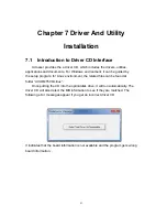
Page 63: ... the setup program for Linux environment the related files can be found at folder AIV HM76V0 Linux Once putting the CD into the optical disk drive it will run automatically The driver CD will also detect the MB information to see if they are matched The following error messages appear if you get an incorrect driver CD It indicates that the board information is not available and the program gets wr...

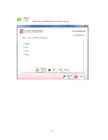
Page 64: ...7 1 1 Driver Page This is the Driver Installation Page 64 ...

Page 65: ...Click the icon all the drivers will be selected 65 ...

Page 66: ...Click the icon all selected items will be cleared 66 ...

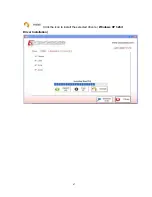
Page 67: ...Click the icon to install the selected drivers Windows XP 32bit Driver Installation 67 ...

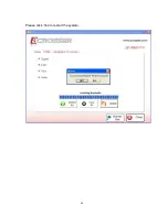
Page 68: ...Please click Yes to restart the system 68 ...

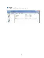
Page 69: ...Click this icon to browse this CD content 69 ...

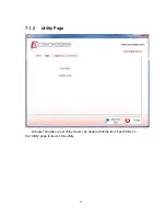
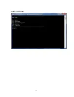
Page 70: ...7 1 2 Utility Page Acrosser provides a test utility Users can double click the item Test Utility on the Utility page to launch this utility 70 ...

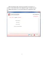
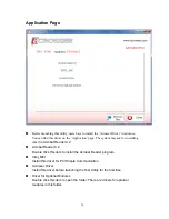
Page 71: ...is utility users have to install the Acrosser Driver in advance You can find this driver on the Application page The system may ask for installing other libraries You can find the libraries on the Application page also 71 ...

Page 72: ...This is the test utility 72 ...

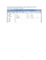
Page 73: ...Users can double click the Sample Code to open the sample code folder The source code of the test utility is in this folder 73 ...

Page 74: ... other lib Acrobat Reader 9 2 Acrobat Reader 9 2 Double click this item to install the Acrobat Reader program Intel_MEI Install this driver for PCI Simple Communication Acrosser Driver Install this driver before launching the Test Utility for the first time Driver for Optional Modules Double click this item to open the folder There are drivers for optional modules in this folder 74 ...

Page 75: ...75 ...

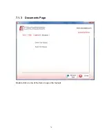
Page 76: ...7 1 3 Documents Page Double click on one of the items to open the manual 76 ...

Page 77: ...ing to load hardware drivers in order to run our product correctly the installation program will automatically enable the test signing feature if it runs under Windows 7 64 bit environment 7 2 1 Installing Drivers Put the Driver Disk into the optical disk drive Then click the Run setup exe to run the install program 77 ...

Page 78: ... The program will appear on the screen Please click the Select All icon 78 ...

Page 79: ...Click the Install icon to install the drivers 79 ...

Page 80: ...system it don t include AHCI driver If you want to install Windows XP operating system in the AHCI mode please follow the steps listed below reference F6Readme txt from folder of the WinXP32_RAID Driver Double click this item to open the folder of the WinXP32_RAID Driver Users need this driver package if they install the Windows XP in the AHCI mode 80 ...

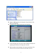
Page 81: ...OS setup enable the AHCI mode of the hard drive Connect the floppy drive to the system before installing the Windows XP operating system Make sure the floppy disk is inserted Boot the system with the installation CD Follow the instructions on the screen As soon as the screen shows this information press F6 81 ...

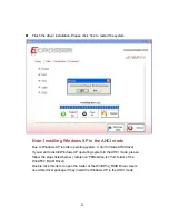
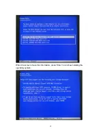
Page 82: ...When the screen shows this information press S When the screen shows a list of available drivers choose the Mobile Express Chipset SATA AHCI Controller 82 ...

Page 83: ...When the screen shows this information press Enter to continue installing the operating system 83 ...

Page 84: ...the CAN packages over the CAN bus 3 Receive the CAN packages via the CAN bus hardware interface 4 Set the CAN package filter to selectively receive CAN packages with specific ID 5 Set the mask bits to selectively make some filter bits take effect 6 Full Mode Enable 7 Full Mode Disable In folder ARB6100 Utility AR V6100_Source on the CD we provides 1 API header file 2 API library in static library ...

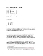
Page 85: ...cket In a Standard Data Frame CAN packet the ID field consists of 11 bits of binary digitals In an Extended Data Frame CAN packet the ID field consists of 29 bits of binary digitals That the CAN packet is a Standard Data Frame packet or an Extended Data Frame packet is determined by the id_type field in the CanMsg variable The id field in the CanMsg variable is a 32 bit long space If a CanMsg vari...

Page 86: ...ruct CanMsg canMsg canMsg id_type EXT_ID A Extended Data Frame packet canMsg id_type STD_ID A Standard Data Frame packet length This field identifies the number of data bytes in the next field data 8 which are filled with effective data Because the data field is an 8 byte long array the range of this field length is 0 8 data 8 This array of data will be filled with effective data For example struc...

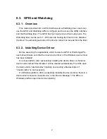
Page 87: ...ng Device Driver Before executing the applications which invoke the GPIO or Watchdog APIs users should make sure that the Linux device driver or the Windows device driver has been installed On Linux platform after successfully installing the device driver a character device node named dev AcroDev will be created automatically The APIs open the device node dev AcroDev implicitly so acquiring a file...

Page 88: ...than the nominal voltage When the voltage is lower than the tolerable voltage the power subsystem turns off the system 7 Get set the Soft Off delay 8 Get set the Hard Off delay 9 Get set the Power On delay 10 Get set the Shutdown delay The power subsystem connects to the main system via the COM port On the Linux platform the actual port number to which the Power Subsystem connects is determined by...

Page 89: ...8 5 I Button Function In the API library we provide a set of I Button functions Users can use the functions to 1 Reset the I Button 2 Read data from the I Button 3 Write data to the I Button 89 ...

Page 90: ...rmation in the memory which is pointed at by the pointer ver Return Value If this function gets the version information successfully it returns 0 any other returned value stands for error 2 Syntax i32 getCanBaudRate u8 baud Descriptions This function gets the current setting of the Baud Rate of the CAN Bus This function gets an unsigned char to represent the Baud Rate Here is the table for the Bau...

Page 91: ...his function gets the baud rate successfully it returns 0 any other returned value stands for error 3 Syntax i32 setCanBaudRate u8 baud Descriptions This function sets the Baud Rate of the CAN Bus Parameters It takes an unsigned char as the parameter and sets the Baud Rate according to the value stored at the parameter baud The correspondence between the Baud rate and the value to set to the funct...

Page 92: ...een initialized The code listed below will send out the CAN packets in the canAry over the CAN bus unsigned int result 0 struct CanMsg canAry 30 Initialize the CAN packages in the canAry 30 result sendCanMessages canAry 30 if result 0 fprintf stderr Send CAN package error n 5 Syntax i32 getCanMessage struct CanMsg buffer u8 count Description This function receives CAN packets from the CAN bus subs...

Page 93: ...o acceptance masks mask0 and mask1 and six acceptance filters filter0 filter5 in the CAN Bus subsystem Filter0 filter1 are associated with mask0 Filter2 filter4 are associated with mask1 Here is the Mask Filter truth table Mask bit n Filter bit n Message ID bit n Accept or reject bit n 0 x x Accept 1 0 0 Accept 1 0 1 Reject 1 1 0 Reject 1 1 1 Accept Note x don t care Parameters This parameter mask...

Page 94: ...e maskId field in a CanMask variable Parameters This functions takes a variable of type CanMask User set the bit patterns they want to the mask field in a CanMask variable struct CanMask u8 maskId 0 or 1 u32 mask For example struct CanMask varMask i32 result varMask maskId 1 varMask mask 0x12345678 result setCanMask varMask Return Value If this function sets the mask setting successfully it return...

Page 95: ...ilter or Extended ID filter struct CanFilter u8 filterId There are six filters so the filterId 0 5 u8 filterType filterType STD_ID or filterType EXT_ID u32 filter If a filter is configured as a Standard ID filter only bit18 bit28 in the mask take effect when filtering the CAN packet Parameters This function takes a pointer to a variable of type CanFilter as the parameter Users set up the filterId ...

Page 96: ...CanFilter varFilter i32 result varFilter filterId 3 varFilter filterType STD_ID varFilter filter 0x555 result setCanFilter varFilter if result 0 printf Fail to set up the filter n Return Value If this function sets the filter successfully it returns 0 any other returned value stands for error 10 Syntax Full Mode Enable Description Enable the Function can receive 11bit and 29bit data Parameters The...

Page 97: ... i32 result result getChLevel val if result 0 printf Fail to get GPIO status n Return Value If the function gets the value successfully it returns 0 any other returned value stands for error 1 Syntax i32 setChLevel u8 val Description Set the status of GPIO Output pins Parameters This function takes an unsigned char as the parameter The bit0 bit3 in variable val represent the status of the output p...

Page 98: ...ter 2 Syntax void setWtdTimer u8 val Description This function sets the watchdog timer register to the value val and starts to count down The value could be 0 255 The unit is second Setting the timer register to 0 disables the watchdog function and stops the countdown Parameters The parameter val is the value to set to watchdog timer register The range is 0 255 Return Value None 8 6 3 Power Subsys...

Page 99: ...inutes Parameters None Return Value If this function works successfully the function will return 0 any other value standards for error 3 Syntax i32 getRemoteSwitch u8 val Description The function gets the status of the Remote Switch Parameters This function takes a pointer to an unsigned char variable as the parameter After calling this function the status of the Remote Switch will be put at the m...

Page 100: ...ed char as the parameter The value of this parameter can be ENABLED 0x5A or DISABLED 0xA5 Return Value If this function works successfully it returns 0 any other value standards for error 5 Syntax i32 getBattValt float vol Description This function gets the battery voltage ant put it in the memory which is pointed at by the pointer vol Parameters This function takes a pointer to a float variable a...

Page 101: ...n works successfully it returns 0 any other value standards for error 7 Syntax i32 setBattMonitor u8 val Description The function sets the status of the Battery Monitor Parameters This function takes an unsigned char as the parameter The value of this parameter can be ENABLED 0x5A or DISABLED 0xA5 Return Value If this function works successfully it returns 0 any other value standards for error 8 S...

Page 102: ...tes a power off signal This function sets up the interval in seconds Parameters The parameter is of the type of unsigned long The value of the parameter ranges from 3 3600 The unit of the value of the parameter is seconds Return Value If this function works successfully it returns 0 any other value stands for error 11 Syntax i32 setHardOffDelay u32 setTime Description The Hard Off Delay is the int...

Page 103: ...ue is in seconds Return Value If this function works successfully the function returns 0 any other value stands for error 13 Syntax i32 getHardOffDelay u32 Time Description The Hard Off Delay is the interval between that the system is off and that the power 5VSB is off This function gets the interval Parameters The parameter is a pointer which points to an unsigned long variable The returned value...

Page 104: ...own delay Parameters This function takes a pointer to an unsigned long variable as the parameter The delay time will be put at the memory which is pointed by the parameter val Return Value If this function works successfully the function returns 0 any other value stands for error 17 Syntax i32 setShutdownDelay u32 val Description This function sets the Shutdown delay Parameters This function takes...

Page 105: ...variable The data to be read from the I Button is put at the memory which is pointed by the parameter data Return Value If this function works successfully the function returns 0 any other value stands for error 3 Syntax i32 writeIbutt u8 data Description This function writes command to the I Button Parameters This function takes an unsigned char variable as the parameter The command to be written...

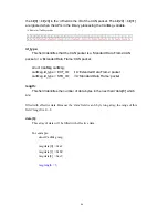
Page 106: ... timeout 5 splashimage hd0 0 grub splash xpm gz hiddenmenu title Fedora Core 2 6 27 5 117 FC10 root hd0 0 kernel vmlinuz 2 6 27 5 117 FC10 ro root dev hda2 rhgb quiet 8250 nr_uarts 6 noirqdebug initrd initrd 2 6 27 5 117 FC10 img 3 List the status of the COM ports in the system setserial g dev ttyS dev ttyS0 UART 16550A Port 0x03f8 IRQ 4 dev ttyS1 UART 16550A Port 0x02f8 IRQ 3 dev ttyS2 UART 16550...

Page 107: ...Appendix B GPIO cable color PIN Color PIN Color 1 Brown 2 Orange 3 Green 4 Blue 5 6 9 Black 8 White 7 Red White 10 Purple 11 Light Green 12 Light Blue 13 Pink 14 Brown White 15 Yellow 107 ...

Reviews: