background image


AR-B1579 

Half Size Pentium(586) 

CPU BOARD


User’s Guide


Edition: 1.2 

Book Number: AR-B1579 


Summary of Contents for AR-B1576

Page 1: ...AR B1579 Half Size Pentium 586 CPU BOARD User s Guide Edition 1 2 Book Number AR B1579 ...

Page 2: ......

Page 3: ... 3 2 3 2 3 Hard Disk IDE Connector 3 3 3 2 4 PC 104 Connector 3 4 3 2 5 Keyboard Connector 3 6 3 2 6 FDD Port Connector CN2 3 7 3 2 7 Parallel Port Connector CN3 3 7 3 2 8 Serial Port 3 8 3 2 9 PS 2 Mouse Connector 3 10 3 2 10 External Speaker Header J1 3 10 3 2 11 Reset Header J8 3 10 3 2 12 Power Connector J9 3 11 3 2 13 LED Header 3 11 3 2 14 CPU Setting 3 11 3 2 15 DRAM Configuration 3 15 3 2 ...

Page 4: ...ing 5 10 5 10 2 Auto Configuration with Fail Safe Setting 5 10 5 11 BIOS EXIT 5 10 5 11 1 Save Settings and Exit 5 10 5 11 2 Exit Without Saving 5 11 5 12 BIOS UPDATE 5 11 6 SPECIFICATIONS 6 1 7 PLACEMENT DIMENSIONS 7 1 7 1 PLACEMENT 7 1 7 2 DIMENSIONS 7 2 8 PROGRAMMING RS 485 INDEX 8 1 8 1 PROGRAMMING RS 485 8 1 8 2 INDEX 8 3 ...

Page 5: ...ve not already installed this AR B1579 refer to the Chapter 3 Setting Up the System in this guide Check the packing list ensure the all accessories in the package The AR B1579 diskette provides the newest information about the card Please refer to the README DOC file of the enclosed utility diskette It contains the latest modification and hardware software information and adding the description or...

Page 6: ...n about static electricity precautions Static electricity is a constant danger to computer systems The charge that can build up in your body may be more than sufficient to damage integrated circuits on any PC board It is therefore important to observe basic precautions whenever you use or handle computer components Although areas with humid climates are much less prone to static build up it is alw...

Page 7: ...V RAM onboard 512KB synchronous pipe line burst SRAM one RS 232C and one RS 232C RS 485 serial port and two 72 pin SIMM connectors which can support up to 128MB of DRAM The AR B1579 is perfect for medical and telecommunications applications factory floor networks use as a MMIs for high speeding processes or a controller for graphics intensive systems 1 2 PACKING LIST The accessories are included w...

Page 8: ...ts from 75MHz to 300MHz Pentium CPUs Up to 128MB DRAM system Up to 512KB PBSRAM L2 cache system On board CRT panel display Supports IDE hard disk drives Supports floppy disk drives Supports 1 bi directional parallel port Supports 2 serial ports RS 232C and RS 485 PC AT compatible keyboard and PS 2 mouse interface Programmable watchdog timer Flash BIOS Built in status LEDs indicator 5V 12V power re...

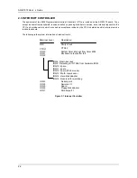
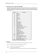
Page 9: ... Controller 1 DMA Controller 2 Channel 0 Spare Channel 4 Cascade for controller 1 Channel 1 IBM SDLC Channel 5 Spare Channel 2 Diskette adapter Channel 6 Spare Channel 3 Spare Channel 7 Spare Table 2 1 DMA Channel Controller 2 2 KEYBOARD CONTROLLER The 8042 processor is programmed to support the keyboard serial interface The keyboard controller receives serial data from the keyboard checks its par...

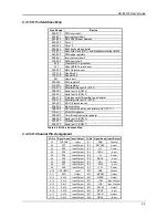
Page 10: ...ch interrupt service routine to execute The following is the system information of interrupt levels IRQ8 Real time clock IRQ9 Rerouting to INT 0Ah from hardware IRQ2 IRQ10 spare IRQ11 spare IRQ12 spare PS 2 mouse IRQ13 Math coprocessor IRQ14 Hard disk adapter IRQ15 Reserved for watchdog In Interrupt Level NMI CTRL1 IRQ 0 IRQ 1 IRQ 2 IRQ 3 IRQ 4 IRQ 5 IRQ 6 IRQ 7 CTRL2 Parity check Description Seri...

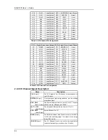
Page 11: ...ous 3B0 3BF Monochrome display and printer port 1 LPT 1 3C0 3CF EGA VGA adapter 3D0 3DF Color Graphics monitor adapter 3E8 3EF Serial port 3 COM 3 3F0 3F7 Diskette controller 3F8 3FF Serial port 1 COM 1 Table 2 2 I O Port Address Map 2 3 2 I O Channel Pin Assignment I O Pin Signal Name Input Output I O Pin Signal Name Input Output A1 IOCHCK Input B1 GND Ground A2 SD7 Input Output B2 RSTDRV Output ...

Page 12: ...16 Input Output D9 DRQ0 Input C10 MWR16 Input Output D10 DACK5 Output C11 SD8 Input Output D11 DRQ5 Input C12 SD9 Input Output D12 DACK6 Output C13 SD10 Input Output D13 DRQ6 Input C14 SD11 Input Output D14 DACK7 Output C15 SD12 Input Output D15 DRQ7 Input C16 SD13 Input Output D16 5V Power C17 SD14 Input Output D17 MASTER Input C18 SD15 Input Output D18 GND Ground Table 2 4 I O Channel Pin Assign...

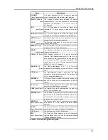
Page 13: ...DMA request priority is in the following sequence Highest DRQ 0 1 2 3 5 6 7 Lowest DACK 0 3 5 7 Output The DMA Acknowledges 0 to 3 5 to 7 are the corresponding acknowledge signals for DRQ 0 to 3 and 5 to 7 AEN output The DMA Address Enable is high when the DMA controller is driving the address bus It is low when the CPU is driving the address bus REFRESH Input Output This signal is used to indicat...

Page 14: ...tatus register D 0E Diagnostic status byte 0F Shutdown status byte 10 Diskette drive type byte drive A and B 11 Fixed disk type byte drive C 12 Fixed disk type byte drive D 13 Reserved 14 Equipment byte 15 Low base memory byte 16 High base memory byte 17 Low expansion memory byte 18 High expansion memory byte 19 2D Reserved 2E 2F 2 byte CMOS checksum 30 Low actual expansion memory byte 31 High act...

Page 15: ...sible register DLAB Port Address Register Receiver buffer read 0 base 0 Transmitter holding register write 0 base 1 Interrupt enable X base 2 Interrupt identification read only X base 3 Line control X base 4 MODEM control X base 5 Line status X base 6 MODEM status X base 7 Scratched register 1 base 0 Divisor latch least significant byte 1 base 1 Divisor latch most significant byte Table 2 7 ACE Ac...

Page 16: ...S Bit 2 Out 1 OUT 1 Bit 3 Out 2 OUT 2 Bit 4 Loop Bit 5 Must be 0 Bit 6 Must be 0 Bit 7 Must be 0 7 Line Status Register LSR Bit 0 Data Ready DR Bit 1 Overrun Error OR Bit 2 Parity Error PE Bit 3 Framing Error FE Bit 4 Break Interrupt BI Bit 5 Transmitter Holding Register Empty THRE Bit 6 Transmitter Shift Register Empty TSRE Bit 7 Must be 0 8 MODEM Status Register MSR Bit 0 Delta Clear to Send DCT...

Page 17: ...1 Table 2 8 Serial Port Divisor Latch 2 5 PARALLEL PORT 1 Register Address Port Address Read Write Register base 0 Write Output data base 0 Read Input data base 1 Read Printer status buffer base 2 Write Printer control latch Table 2 9 Registers Address 2 Printer Interface Logic The parallel portion of the SMC37C669 makes the attachment of various devices that accept eight bits of parallel data at ...

Page 18: ...is off line during printing or when the print head is changing position or in an error state When Bit 7 is active the printer is busy and can not accept data Bit 6 This bit represents the current state of the printer s ACK signal A0 means the printer has received the character and is ready to accept another Normally this signal will be active for approximately 5 microseconds before receiving a BUS...

Page 19: ...put buffers in the parallel port are disabled allowing data driven from external sources to be read when logic 0 they work as a printer port This bit is write only Bit 4 A1 in this position allows an interrupt to occur when ACK changes from low state to high state Bit 3 A1 in this bit position selects the printer Bit 2 A0 starts the printer 50 microseconds pulse minimum Bit 1 A1 causes the printer...

Page 20: ......

Page 21: ...setting Overview System Setting 3 1 OVERVIEW The AR B1579 is Pentium single CPU board This section provides hardware s jumpers settings connectors locations and the pin assignments Figure 3 1 External System Location SW1 CN1 J1 J5 CN4 CN6 JP2 J6 DB1 JP4 J8 JP4 JP3 J7 J9 J11 U11 J12 DB2 U5 JP5 J10 JP6 CN8 CN7 J12 CN9 SW2 CN2 CN3 JP1 J3 J4 ...

Page 22: ... your fingers can permanently damage electronic components 3 2 1 CRT CONNECTOR DB1 The AR B1579 supports CRT color monitors It can be connected to create a compact video solution for the industrial environment It allows a maximum CRT resolution of 1024X768 For different VGA display modes your monitor must possess certain characteristics to display the mode you want To connect to a CRT monitor an a...

Page 23: ... following table illustrates the pin assignments of the hard disk drive s 40 pin connector 1 2 40 39 Figure 3 4 CN1 Hard Disk IDE Connector Pin Signal Pin Signal 1 RESET 2 GROUND 3 DATA 7 4 DATA 8 5 DATA 6 6 DATA 9 7 DATA 5 8 DATA 10 9 DATA 4 10 DATA 11 11 DATA 3 12 DATA 12 13 DATA 2 14 DATA 13 15 DATA 1 16 DATA 14 17 DATA 0 18 DATA 15 19 GROUND 20 NOT USED 21 IDEDRQA 22 GROUND 23 IOW A 24 GROUND ...

Page 24: ...28 A29 A30 A31 A32 GND RSTDRV 5 VDC IRQ9 5 VDC DRQ2 12 VDC ZWS 12 VDC GND SMEMW SMEMR IOW IOR DACK3 DRQ3 DACK1 DRQ1 REFRESH BUSCLK IRQ7 SA9 SA8 SA7 SA6 SA5 SA4 SA3 SA2 SA1 SA0 GND B1 B2 B3 B4 B5 B6 B7 B8 B9 B10 B11 B12 B13 B14 B15 B16 B17 B18 B19 B20 B21 B22 B23 B24 B25 B26 B27 B28 B29 B30 B31 B32 IRQ6 IRQ5 IRQ4 IRQ3 DACK2 TC BALE 5 VDC OSC GND GND CN8 1 2 Figure 3 5 CN8 64 Pin PC 104 Connector Bu...

Page 25: ...ice to drive its data onto the data bus IOW Input Output The I O write signal is an active low signal which instructs the I O device to read data from the data bus SMEMR Output The System Memory Read is low while any of the low 1 mega bytes of memory are being used MEMR Input Output The Memory Read signal is low while any memory location is being read SMEMW Output The System Memory Write is low wh...

Page 26: ...1 wait state 16 bit data I O operation OSC Output The Oscillator is a 14 31818 MHz signal used for the color graphic card ZWS Input Open collector The Zero Wait State indicates to the microprocessor that the present bus cycle can be completed without inserting additional wait cycle Table 3 2 I O Channel Signal Description 3 2 5 Keyboard Connector 1 Keyboard Lock Header J7 1 2 KBLK GND 1 2 Figure 3...

Page 27: ...l Port Connector CN3 To use the parallel port an adapter cable has to be connected to the CN3 26 pin header type connector This adapter cable is mounted on a bracket and is included in your AR B1579 package The connector for the parallel port is a 25 pin D type female connector 1 2 1 14 13 25 D Type Connector Parallel Port Connector 25 26 Figure 3 11 CN3 Parallel Port Connector CN3 DB 25 Signal CN...

Page 28: ... Adapter Select JP4 Reserved for RS 485 Adapter Used 1 2 3 RS 232 1 2 3 Factory Default Figure 3 12 JP4 COM A RS 485 Adapter Select B COM B RS 485 Adapter Select JP2 Reserved for Acrosser s RS 485 Adapter Used Only 1 2 3 RS 232C 1 2 3 Factory Default Setting Figure 3 13 JP2 COM B RS 485 Adapter Select C COM B RS 232C RS 485 Select SW1 8 ON 1 2 3 4 5 6 OFF SW1 8 RS 232 Factory Default Setting 7 8 O...

Page 29: ...232C interface on the AR B1579 COM A uses one onboard D type 9 pin male connector DB2 and COM B uses one 10 pin header CN4 which are located at the right side of the card To configure these two serial ports use the BIOS Setup program and adjust the jumpers on JP1 and JP4 The pin assignments of the DB2 and CN4 for serial port A B are as follows Figure 3 17 DB2 CN4 RS 232 Connector CN3 DB2 Signal CN...

Page 30: ...e used 2 PS 2 Mouse Connector CN5 J6 To use the PS 2 interface an adapter cable has to be connected to the J6 6 pin header type connector This adapter cable is mounted on a bracket and is included in your AR B1579 package The connector for the PS 2 mouse is a Mini DIN 6 pin connector Pin assignments for the PS 2 port connector are as follows Figure 3 19 CN5 J6 PS 2 Mouse Connector 3 2 10 External ...

Page 31: ... LED Header 3 2 14 CPU Setting The AR B1579 accepts many types of 586 microprocessors such as Intel Pentium AMD K5 AMD K6 and Cyrix 6X86 All of these CPUs include an integer processing unit floating point processing unit memory management unit and cache They can give a two to ten fold performance improvement in speed over the 486 processor depending on the clock speeds used and specific applicatio...

Page 32: ...ration clock SW1 4 SW1 5 SW1 6 Base Clock PCI Clock ON ON OFF 50MHz 25MHz OFF ON OFF 66 6MHz 33 3MHz ON OFF OFF 60MHz 30MHz OFF OFF OFF 55MHz 27 5MHz OFF OFF ON 75MHz 37 5MHz ON 1 2 3 4 5 6 OFF Clock Multiplier 7 8 D O C RS 485 Table 3 6 SW1 CPU Clock Multiplier 2 CPU Clock Multiplier Select SW1 The CPU clock multiplier needs to be set by SW1 ON 1 2 3 4 5 6 OFF Multiplier BF0 BF1 BF2 7 8 Figure 3 ...

Page 33: ...ctory Preset 1 2 3 4 6 5 Figure 3 30 JP5 P55C P54C CPU Type Select Intel CPU SW1 SW1 1 SW1 2 SW1 3 CPU Type Work Frequency Clock Multiplier BF0 BF1 BF2 SW2 Pentium 75 75MHz 50 0MHz 1 5X Off Off Off 3 36V Pentium 90 90MHz 60 0MHz 1 5X Off Off Off Pentium 100 100MHz 66 7MHz 1 5X Off Off Off Pentium 120 120MHz 60 0MHz 2 0X On Off Off Pentium 133 133MHz 66 7MHz 2 0X On Off Off Pentium 150 150MHz 60 0M...

Page 34: ... BF0 BF1 BF2 SW2 6X86 PR100 80MHz 40 0MHz 2 0X On Off Off 3 36V 6X86 PR120 100MHz 50 0MHz 2 0X On Off Off 6X86 PR133 110MHz 55 0MHz 2 0X On Off Off 6X86 PR150 120MHz 60 0MHz 2 0X On Off Off 6X86 PR166 133MHz 66 7MHz 2 0X On Off Off 6X86 PR200 150MHz 75 0MHz 2 0X On Off Off 6X86L PR120 100MHz 50 0MHz 2 0X On Off Off 2 86V 6X86L PR133 110MHz 55 0MHz 2 0X On Off Off 6X86L PR150 120MHz 60 0MHz 2 0X On...

Page 35: ... is right 3 2 16 D O C Memory Address Select SW1 7 This section provides the information about how to use the D O C DiskOnChip There divided two parts hardware setting and software configuration Step 1 Use SW1 7 to select the correct D O C memory address Step 2 Insert programmed DiskOnChip into sockets U10 setting as DOC Step 3 Line up and insert the AR B1579 card into any free slot of your comput...

Page 36: ......

Page 37: ...e sure that the FDC HDC serial and parallel cables are connected to pin 1 of the related connector Step 7 Connect the hard disk floppy disk flat cables from the CPU card to the drives Connect a power source to each drive Step 8 Plug the keyboard into the keyboard connector Step 9 Turn on the power Step 10 Configure your system with the BIOS Setup program then re boot your system Step 11 If the CPU...

Page 38: ...te message and the SiS Multimedia V1 07 program folder And in the program folder user can find only one uninstall icon Step 8 In Main Group program folder the Windows setting item we can find the Display item will appear SiS 5597 5598 640x480 256 colors and other SiS 5597 5598 resolution colors font size and so on User can adjust the item for the VGA mode in WIN31 4 2 2 WIN 95 Driver For the WIN95...

Page 39: ...ort must be installed 2 If you previously installed SVGA support you must do the following a Close all DOS Full Screen and WIN OS2 sessions b Reset the system to VGA mode VGA is the default video mode enabled when OS 2 is installed To restore VGA mode use Selective Install and select VGA for Primary Display For more information on this procedure see the section on Changing Display Adapter Support ...

Page 40: ...chdog timer is automatically disabled after reset Once you have enabled the watchdog timer your program must trigger the watchdog timer every time before it times out After you trigger the watchdog timer it will be set to zero and start to count again If your program fails to trigger the watchdog timer before time out it will generate a reset pulse to reset the system or trigger the IRQ15 signal t...

Page 41: ...chdog Transferring Select JP6 Figure 4 2 JP6 Watchdog Transferring Select 4 3 3 Watchdog Timer Enabled To enable the watchdog timer you have to output a byte of timer factor to the watchdog register whose address is 76H or Base Port 4 The following is a BASICA program demonstrates how to enable the watchdog timer and set the time out period at 24 seconds 1000 REM Points to command register 1010 WD...

Page 42: ...d To disable the watchdog timer simply write a 00H to the watchdog register 3000 REM Points to command register 3010 WD_REG BASE_PORT 4 3020 REM Timer factor 0 3030 TIMER_FACTOR 0 3040 REM Output factor to watchdog register 3050 OUT WD_REG TIMER_FACTOR etc ...

Page 43: ...cilitates interaction between the system hardware and the operating system The BIOS default values ensure that the system will function at its normal capability In the worst situation the user may have corrupted the original settings set by the manufacturer After the computer is turned on the BIOS will perform diagnostics on the system and display the size of the memory that is being tested Press ...

Page 44: ...egatrends Inc All Rights Reserved Date mm dd yyyy Tue Jun 01 1999 640KB Time hh mm ss 13 39 30 63MB Floppy Drive A 1 44MB 3 1 2 Floppy Drive B Not Installed LBA Blk PIO 32Bit Type Size Cyln Head Wpcom Sec Mode Mode Mode Mode Pri Master Auto Off Off Auto Off Pri Slave Auto Off Off Auto Off Sec MASTER Auto Off Off Auto Off Sec Slave Auto Off Off Auto Off Boot Sector Virus Protection Disabled Month J...

Page 45: ...ating systems requires that you disable this to prevent write errors 5 3 ADVANCED CMOS SETUP The Advanced CMOS Setup option consists of configuration entries that allow you to improve your system performance or let you set up some system features according to your preference Some entries here are required by the CPU board s design to remain in their default settings AMIBIOS SETUP ADVANCED CMOS SET...

Page 46: ...Floppy Drive Seek If the Floppy Drive Seek item is setting Enabled the BIOS will seek the floppy A drive one time upon bootup PS 2 Mouse Support The setting of Enabled allows the system to detect a PS 2 mouse on bootup If detected IRQ12 will be used for the PS 2 mouse IRQ 12 will be reserved for expansion cards if a PS 2 mouse is not detected Disabled will reserve IRQ12 for expansion cards and the...

Page 47: ...the write back caching algorithm WriteThru Use the write through caching algorithm Table 5 1 Internal Cache Setting L2 Cache This option specifies the caching algorithm used for L2 secondary external cache memory The settings are Setting Description Disabled Neither L1 internal cache memory on the CPU or L2 secondary cache memory is enabled WriteBack Use the write back caching algorithm WriteThru ...

Page 48: ...vious screen AMIBIOS SETUP ADVANCED CHIPSET SETUP C 1998 American Megatrends Inc All Rights Reserved USB Function Enabled USB KB Mouse Legacy Support Disabled DRAM Automatic Configuration Disabled EDO Dram Access Time 60ns FP Dram Access Time None Used Refresh Cycle Time 62 4us RAS Pulse Width When Refresh 4T DRAM Read Leadoff Time 1T ISA Bus Clock Frequency 7 159MHZ MEMORY HOLE at 15M 16M Disable...

Page 49: ...te Disabled Standby Time Out Minute Disabled Suspend Time Out Minute Disabled Slow Clock Ratio 1 4 IRQ 3 COM2 COM4 Monitor IRQ 4 COM1 COM3 Monitor IRQ 5 LPT 2 Ignore IRQ 7 LPT 1 Monitor IRQ 9 Ignore IRQ 10 Ignore IRQ 11 Ignore IRQ 12 PS2 Mouse Monitor IRQ 14 Monitor IRQ 15 Monitor Available Options Disabled Enabled ESC Exit Sel PgUp PgDn Modify F2 F3 Color Figure 5 5 BIOS Power Management Setup Po...

Page 50: ...Timer PCI Clocks 64 PCI IDE BusMaster Disabled DMA Channel 0 PnP DMA Channel 1 PnP DMA Channel 3 PnP DMA Channel 5 PnP DMA Channel 6 PnP DMA Channel 7 PnP IRQ 3 ISA EISA IRQ 4 ISA EISA IRQ 5 PCI PnP IRQ 7 ISA EISA IRQ 9 PCI PnP IRQ 10 PCI PnP IRQ 11 PCI PnP IRQ 12 PCI PnP IRQ 14 PCI PnP IRQ 15 PCI PnP Reserved Memory Size Disabled Reserved Memory Address C8000 Available Options Yes No ESC Exit Sel...

Page 51: ... used to configure peripheral features AMIBIOS SETUP PERIPHERAL SETUP C 1998 American Megatrends Inc All Rights Reserved OnBoard FDC Enabled OnBoard Serial Port1 3F8h COM1 OnBoard Serial Port2 2F8h COM2 OnBoard Parallel Port 378h Parallel Port Mode ECP Parallel Port IRQ N A Parallel Port DMA Channel 3 OnBoard PCI IDE Both Primary Master Prefetch Enabled Primary Slave Prefetch Enabled Secondary Mas...

Page 52: ...uration parameters you can choose a group of settings that have a better chance of working when the system is having configuration related problems 5 10 1 Auto Configuration with Optimal Setting The user can load the optimal default settings for the BIOS The Optimal default settings are best case values that should optimize system performance If CMOS RAM is corrupted the optimal settings are loade...

Page 53: ...p 5 And then please enter the file name to the box of Enter File Name And the box of Message will show the notice as follow In the bottom of this window always show the gray statement Flash EPROM Programming is going to start System will not be usable until Programming of Flash EPROM is successfully complete In case of any error existing Flash EPROM must be replaced by new program Flash EPROM Step...

Page 54: ......

Page 55: ...l centronics type parallel port Supports SPP EPP ECP mode Serial Port 1 RS 232C and 1 RS 232C RS 485 Keyboard PC AT compatible keyboard and PS 2 mouse interface FLASH Disk Supports 1 socket for up to 72MB DiskOnChip Watchdog Programmable watchdog timer Speaker On board Buzzer and external speaker Real Time Clock BQ3287MT or compatible chips with 128 bytes data RAM BIOS AMI Flash BIOS 256KB includi...

Page 56: ......

Page 57: ...AR B1579 User s Guide 7 1 7 PLACEMENT DIMENSIONS 7 1 PLACEMENT CN7 JP5 SW2 U5 JP6 BUS2 BUS1 J10 CN8 U4 J1 J5 SW1 DIMM1 CN1 J6 CN9 J12 DB2 J11 J9 JP4 JP3 J7 J8 CN4 CN2 CN3 JP2 DB1 CN6 CN5 J4 JP1 J3 ...

Page 58: ...MENSIONS 265 3590 445 2635 255 370 95 210 1300 345 900 4100 940 7 138 7 138 7 138 7 138 825 600 3950 25 4800 7280 130 825 150 600 450 300 210 95 1700 400 210 95 3000 905 930 4150 3150 455 4000 1100 125 Unit mil 1 inch 25 4 mm 1000 mil ...

Page 59: ...aracter Transmit Step 1 Enable TXC signal and the bit 0 of the address of offset 4 just sets 1 Step 2 Send out the data Write this character to the offset 0 of the current COM port address Step 3 Wait for the buffer s data empty Check transmitter holding register THRE bit 5 of the address of offset 5 and transmitter shift register TSRE bit 6 of the address of offset 5 are all sets must be 0 Step 4...

Page 60: ...NP H3FC OR H01 30 REM Send out one character 40 PRINT 1 OUTCHR 50 REM Check transmitter holding register and shift register 60 IF INP H3FD AND H60 0 THEN 60 70 REM Disable transmitter by resetting DTR 80 OUT H3FC INP H3FC AND HEF 90 RETURN c Receive one character from COM1 10 REM Check COM1 receiver buffer 20 IF LOF 1 256 THEN 70 30 REM Receiver buffer is empty 40 INPSTR 50 RETURN 60 REM Read one ...

Page 61: ...COM B RS 232C RS 485 select 3 8 System base clock CPU clock multiplier 3 12 SW1 D O C memory address select 3 15 SW2 CPU logic core voltage select 3 13 JP2 COM B RS 485 adapter select 3 8 JP1 RS 485 terminator select 3 9 JP3 PS 2 mouse IRQ12 setting 3 10 JP4 COM A RS 485 adapter select 3 8 JP6 Watchdog transferring select 3 2 JP5 P54C P55C CPU type select 3 13 Caution on activating USB devices Mod...

Reviews: