ACROSSER TECHNOLOGY
38
The following is a brief description of the adjustment
procedure.
1. Run calibration program B3001DM.EXE which is
provided in the supplemental diskette. Input the base
address of your AR-B3001 according to the setting of
DIP SW.
2. Apply an analog input of 1.22 mV to the analog input
channel 0. Adjust the A/D offset potential meter(VR4)
until the reading is equal to 1.
3. Apply an analog input of 2.5V and adjust the full-scale
pot (VR1 and VR2) for a reading of 2.5V. Other inputs
such as 1.25V and 3.75V can be applied to check the
linearity.
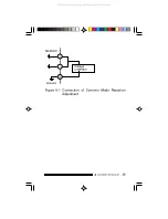
4. If differential input mode is used, the adjustment of a
common mode rejection has to be made. Short the
HIGH and LOW input of A/D channel 0 and connect
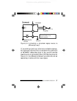
them to a voltage calibrator as in figure 6-1. The
voltage calibrator should be varied from 0 to + or -5
volts. Adjust the A/D common mode potential meter
(VR5) so that the reading of A/D does not change.
All manuals and user guides at all-guides.com


