background image

Compressed Air Dryer                     

 882.03168.00 

2/13/2023 

17 

Chapter 3:  

Installation 

3-1  Uncrating the Equipment 

The compressed air dryer has a handle at the top of the cabinet to use for lifting. For 
hopper-mount configurations, be sure to support the hopper when lifting and placing the 
dryer. Use caution and observe safety rules when lifting and placing your dryer. Be sure it is 
securely attached and additional bracing is used if necessary. 

3-2  Connecting a Hopper-Mount Dryer to a Hopper 

When mounting the dryer to an existing hopper, use the adapter and the self-tapping 
screws that are provided with the unit to mount the dryer to the inlet of the hopper.  The 
adapter is pre-drilled with three holes that are used to mount it to the hopper.   

Note:


In some cases, depending on the drying hopper model, an adapter may not be 
required. If an adapter is not required, attach the dryer to the hopper with the 
clamps provided, and install the exhaust filter to the drying hopper 
outlet/return line. 

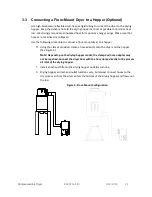
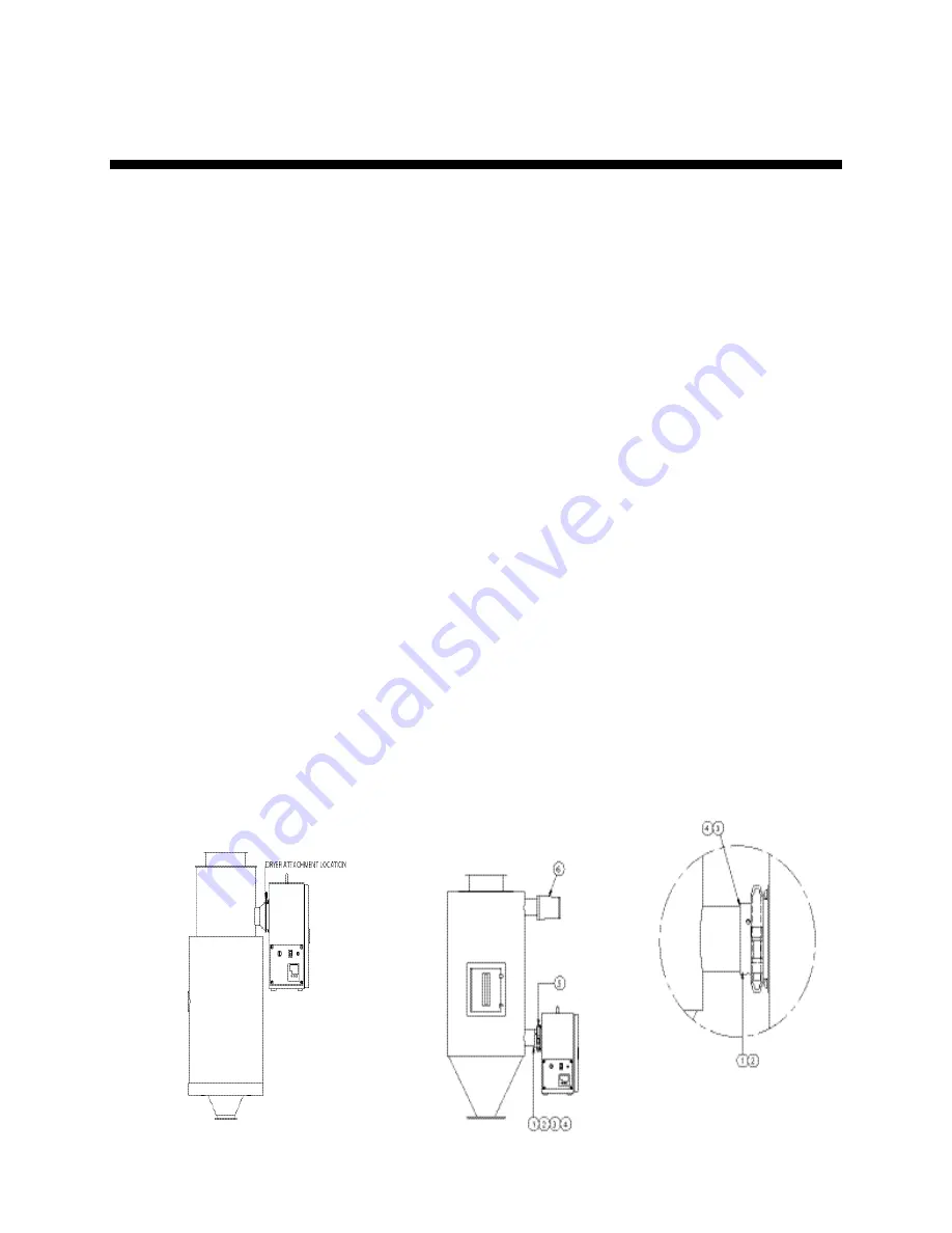
Use the following procedure to mount the dryer to a hopper using an adapter (See Figure 3): 

1.


Mark the holes in the inlet tube of the hopper for drilling. 

2.


Use a 9/64” drill bit to pre

-drill for the #8-32 screws that are provided. 

3.


Spread silicone adhesive over the area where the adapter will mount to the hopper inlet 
tubing. 

4.


Place the adapter onto the tubing and install the three screws to hold it in place. Allow 
sufficient time for the silicone to cure before you operate the dryer. 

5.


Attach the dryer to the hopper with the clamps provided. 

6.


Install an exhaust filter to the drying hopper outlet/return line. 


Figure 3: Typical Hopper-Mount Configuration 


Summary of Contents for ACD10

Page 1: ...Compressed Air Dryer 882 03168 00 2 13 2023 1 Compressed Air Dryer Part Number 882 03168 00 Effective 02 13 2023 Bulletin Number DRY1 600 00 OPERATION AND INSTRUCTION MANUAL MODELS ACD SCD...

Page 2: ..._________________________ _________________________ _________________________ _________________________ _________________________ We are committed to product improvement Specifications appearance and...

Page 3: ...ged Freight ACS must be notified within 24 hours of any damage The driver should give you a claim number before they leave your facility If the order is collect or third party billing to a customer s...

Page 4: ...ial to see if you missed any smaller items during unpacking If the Shipment is Not Correct If the shipment is not what you ordered contact the shipping department immediately Please call 262 641 8600...

Page 5: ...al Connections Error Bookmark not defined 3 3 Making Electrical Connections 18 3 4 Initial Start up 19 CHAPTER 4 OPERATION 21 4 1 Start up 21 4 2 Operation Procedures Error Bookmark not defined 4 3 Sh...

Page 6: ...in addition to information for operating the machine safely and efficiently The Maintenance chapter is intended to serve as a source of detailed assembly and disassembly instructions for those areas o...

Page 7: ...C70 standards 1 3 Responsibility These machines are constructed for maximum operator safety when used under standard operating conditions and when recommended instructions are followed in the maintena...

Page 8: ...hase electrical power Use caution when using or maintaining this product Every six months inspect all electrical connections for secure attachment For further information see the Maintenance Chapter i...

Page 9: ...standards for performing a lock out tag out procedure Lock out power whenever worked on to prevent electrical shock Safety Gloves Required Wear gloves to prevent injury when performing maintenance wor...

Page 10: ...safety hazards SAFE HOUSEKEEPING The work area must be kept clean and uncluttered during periods of operation or maintenance No hand tools or other metal objects should be left on or around the machin...

Page 11: ...o the machine before performing any service SAFETY INTERLOCKS MUST NOT BE BYPASSED The mechanical and electrical safety interlocks ensure the safety of personnel They should never be tampered with or...

Page 12: ...w point air heated to a controlled temperature for drying plastic pellets and regrind Many variables were considered in the selection of your drying system including type of materials residence time t...

Page 13: ...uted to the establishment of safety standards that apply to the design and manufacture of automated equipment The Occupational Safety and Health Administration OSHA and the Joint Industrial Council JI...

Page 14: ...of approved electrical lockout tags These tags are available at most electrical supply stores Always disconnect power before servicing or moving this unit DANGER At no time should anyone remove the lo...

Page 15: ...econd plastic that actually separates the water vapor from the air This second coating allows air to pass through it over 20 000 times easier than it allows water to pass As a result moisture is expel...

Page 16: ...t that you can remove from the mounting housing All parameters except for the process air set point are factory set and adjusted Normally no field adjustment to the internal controls is necessary Figu...

Page 17: ...to the hopper Note In some cases depending on the drying hopper model an adapter may not be required If an adapter is not required attach the dryer to the hopper with the clamps provided and install...

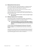
Page 18: ...wing procedure to connect a floor mount dryer to a hopper 0 Using the clamps provided clamp a hose adaptor onto the dryer and the hopper See Figure 4 Note Depending on the drying hopper model the clam...

Page 19: ...lated to 80 PSI 5 5 bars Low air pressure will create poor drying performance If the pressure in the system drops below 35 PSI the alarm light will activate and the process heater and solenoid valve w...

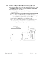
Page 20: ...inlet of the compressed air dryer 2 Attach the large particle filter including the close nipple to the membrane drying kit Note The membrane drying kit must have the large particle and the coalescing...

Page 21: ...uning the Dryer Although the controller is calibrated at the factory the unit should be auto tuned prior to dryer start up Use the following procedure to auto tune the dryer 1 Select operator level 2...

Page 22: ...ON OFF switch to ON to energize the display panel and turn on the solenoid and the heater 5 Use the Up Arrow and Down Arrow buttons to set the process set point on the temperature controller Note To a...

Page 23: ...ity 5 2 Cleaning and Replacing the Filters The compressed air dryer uses a large particle air filter in the process air system to clean the compressed air before it enters the drying cabinet The optio...

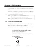
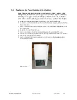
Page 24: ...ake sure that the main power to the dryer is shut off and locked out 2 Locate the fuse holder that houses the fuse for the dryer see picture below for fuse holder location 3 Using a standard flat head...

Page 25: ...necessary functions Before making haphazard substitutions and repairs when electrical components have malfunctioned we recommend that you check the associated circuitry and assemblies for other defect...

Page 26: ...it settings Process thermocouple not in airflow Verify that the thermocouple is properly installed in the inlet tube No setting change possible on temperature controller The internal mechanism is not...

Page 27: ...ssible Cause Possible Remedy Alarm light is on and unit has no air pressure Compressed air source is no longer sufficiently above 35 psi Check compressed air source for proper functioning Regulator is...

Page 28: ...which a purchaser may be liable to other persons damages to property or injuries to any other persons Our sole obligation under this warranty shall be limited to replacing repairing or exchanging any...

Page 29: ...23 29 Refer to this manual for assistance in installing and maintaining a highly efficient machine Questions regarding areas that are not covered in the manual should be referred to the customer servi...

Page 30: ...bilities up to 400 F Large particle compressed air filter Exhaust air cartridge filter 1 16 DIN PID temperature controller High process temperature alarm light Automatic shutoff system to monitor comp...

Page 31: ...2 8 1 3 6 3 2 9 PA12 167 75 4 6 0 7 0 07 2 8 1 3 6 3 2 9 PA6 176 80 4 6 0 5 0 05 2 8 1 3 6 3 2 9 PA6 6 176 80 4 6 0 5 0 05 2 8 1 3 6 3 2 9 PA6 6 GF35 176 80 4 6 0 5 0 04 2 8 1 3 6 3 2 9 PBT 266 130 3...

Page 32: ...80 3 4 0 4 0 01 4 6 2 1 16 4 7 4 PVC 158 70 1 2 0 3 0 10 9 3 4 2 41 9 19 SAN 176 80 2 3 0 3 0 03 5 6 2 5 25 2 11 4 SB 176 80 2 0 3 0 03 7 3 2 31 5 14 3 TPE 230 110 3 4 4 6 2 1 16 4 7 4 TPU 194 90 2 3...

Page 33: ...arts not included in this list must be replaced by the factory Part No Quantity Description 35452 1 Filter Regulator 725 00002 00 1 Fuse 110 volt 725 00001 00 1 Fuse 220 1 50 725 00001 00 2 Fuse 230 1...

Page 34: ...er please have the model and serial number of your unit ready when you contact us TECHNICAL ASSISTANCE If you require any technical assistance we have a qualified service department ready to help We a...

Reviews: