Compact FLASH III Digital Audio System
Copyright©1992-2007 by ACS, Sarasota, Florida
25
ALL RIGHTS RESERVED
CFSound III Contact Sense 24 Module
This module provides twenty four contact inputs. The contacts are numbered 1 through 24 and are
associated with sound files named 01.WAV through 18.WAV.
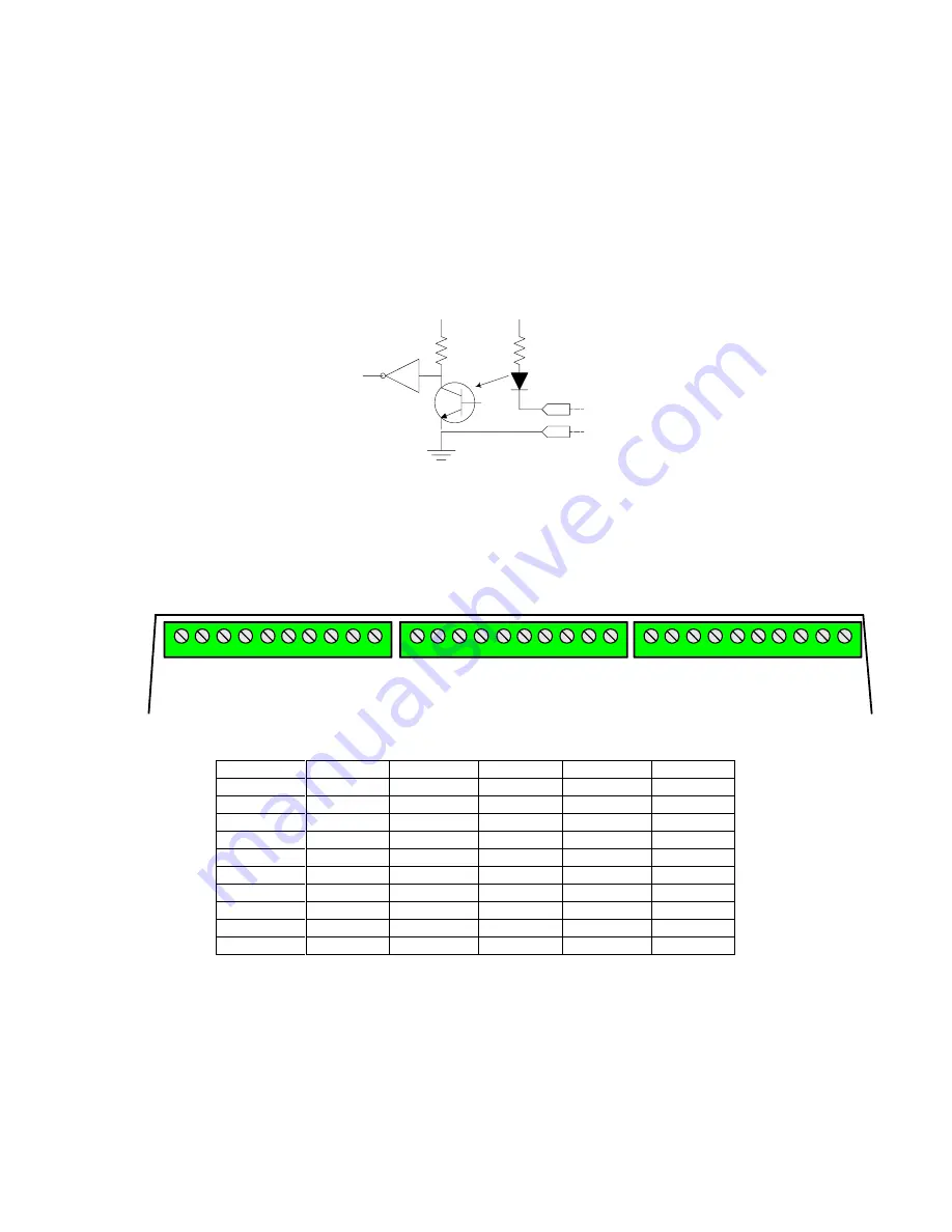
The Cathodes of the LEDs in the optocouplers are connected to the Input connector port pins. The
Anodes of the LEDs in the optocouplers are connected to an internal 12VDC power supply, with a 680
ohm current limiting resistor in series. The output transistor of each optocoupler has a 10K pullup resistor
on its collector, with the emitter connected to ground and is buffered by an inverting gate. The following
diagram is representative of one input:
INPUTx
GROUND
VEE
+5v
680
ohm
10K
ohm
An input is activated by sinking current from the corresponding input pin to ground. A Ground
connection is supplied on pins 1 and 10 of each Input connector for this purpose. The input current sink
requirement is approximately 15 mA.
The Input connectors INP1, INP2 and INP3 consist of three 10 pin, 2 piece terminal block style
connectors mounted adjacently. The pinout is shown in the following diagram and table:
IN
P
U
T
8
IN
P
U
T
7
IN
P
U
T
6
IN
P
U
T
5
IN
P
U
T
4
IN
P
U
T
3
IN
P
U
T
2
G
R
O
U
N
D
IN
P
U
T
1
G
R
O
U
N
D
1
2
3
4
5
6
7
8
9
10
IN
P
U
T
1
6
IN
P
U
T
1
5
IN
P
U
T
1
4
IN
P
U
T
1
3
IN
P
U
T
1
2
IN
P
U
T
1
1
IN
P
U
T
1
0
G
R
O
U
N
D
IN
P
U
T
9
G
R
O
U
N
D
1
2
3
4
5
6
7
8
9
10
IN
P
U
T
2
4
IN
P
U
T
2
3
IN
P
U
T
2
2
IN
P
U
T
2
1
IN
P
U
T
2
0
IN
P
U
T
1
9
IN
P
U
T
1
8
G
R
O
U
N
D
IN
P
U
T
1
7
G
R
O
U
N
D
1
2
3
4
5
6
7
8
9
10
INP3
INP2
INP1
INP3 Pin #
Signal
INP2 Pin #
Signal
INP1 Pin #
Signal
1
GROUND
1
GROUND
1
GROUND
2
INPUT17
2
INPUT9
2
INPUT1
3
INPUT18
3
INPUT10
3
INPUT2
4
INPUT19
4
INPUT11
4
INPUT3
5
INPUT20
5
INPUT12
5
INPUT4
6
INPUT21
6
INPUT13
6
INPUT5
7
INPUT22
7
INPUT14
7
INPUT6
8
INPUT23
8
INPUT15
8
INPUT7
9
INPUT24
9
INPUT16
9
INPUT8
10
GROUND
10
GROUND
10
GROUND


