30
Eubank Wall Mount Heat Pump I&O Manual
05/2023 Rev.2
(10)
3/8" mounting bolts
or lag screws for side brackets and anchors, if required for side brackets.
(20)
3/8" washers
(10)
3/8" hex nuts
(6)
3/8" x 2-1/2" lag screws
for bottom bracket
•
Silicone Sealer
to seal around cracks and openings
•
7-conductor low voltage multi-colored wire cable
(i.e. thermostat wire)
•
Appropriate electrical supplies
such as
conduit, electrical boxes, fittings, wire connectors,
etc.
•
High voltage wire
, sized to handle the MCA (minimum circuit ampacity) listed on the data plate.
•
Over-Current Protection Device
sized in accordance with the MFS (maximum fuse size) listed on
the unit data plate.
Duct materials usually are also needed in addition to the mounting hardware. To save time, design the
duct work before mounting the unit.
3.4 Porting and Duct Work
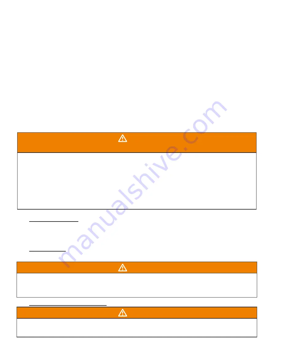
WARNING
FIRE HAZARD
Improper adjustment, alteration, service, maintenance or installation could cause serious
injury, death and/or property damage.
Installation or repairs made by unqualified persons could result in hazards to you and
others. Installation MUST conform with local codes or, in the absence of local codes, with
codes of all governmental authorities have jurisdiction.
The information contained in this manual is intended for use by a qualified service
agency that is experienced in such work, is familiar with all precautions and safety
procedures required in such work, and is equipped with the proper tools and test
instruments.
General Information
Note:
The following instructions are for general guidance only. Due to the wide variety of installation
possibilities, specific instructions will not be given. When in doubt, follow standard and accepted
installation practices, or contact Eubank
®
for additional assistance.
Wall Openings
Measure the dimensions of the supply and return openings on the heat pump unit.
WARNING
Cut the supply opening in the exterior wall for the supply and return.
IMPORTANT: All units must
have one inch clearance on all four sides of the supply outlet duct flange on the unit. The
one inch clearance must extend on all sides of the supply duct for the first three feet from
the unit.
The duct must be constructed of galvanized steel with a minimum thickness of .019".
Minimum Airflow Requirements
WARNING
The duct system must be engineered to assure sufficient air flow through the Heat Pump, even
under adverse conditions such as dirty filters, etc. Proper engineering will insure longevity and
maximum performance from the Heat Pump unit.


