background image

39

Eubank Wall Mount Heat Pump I&O Manual

05/2023 Rev.2

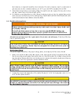
4.4  Ventilation System Set-Up:


Manual Fresh Air System (Configuration N)

. This is the standard ventilation system in Eubank heat 

pumps. Fresh air ventilation by means of a damper can provide up to 15% of rated air flow of outside 

air. The damper has four positions corresponding to 0, 5, 10 and 15% of rated air flow of outside air.

  The damper only opens when the indoor fan is operating. Position the screw on the side of the damper 

hood for the desired air flow.

   Manual Damper - 0 to 450 cfm of Outside Air, No Pressure Relief (Configuration Y).


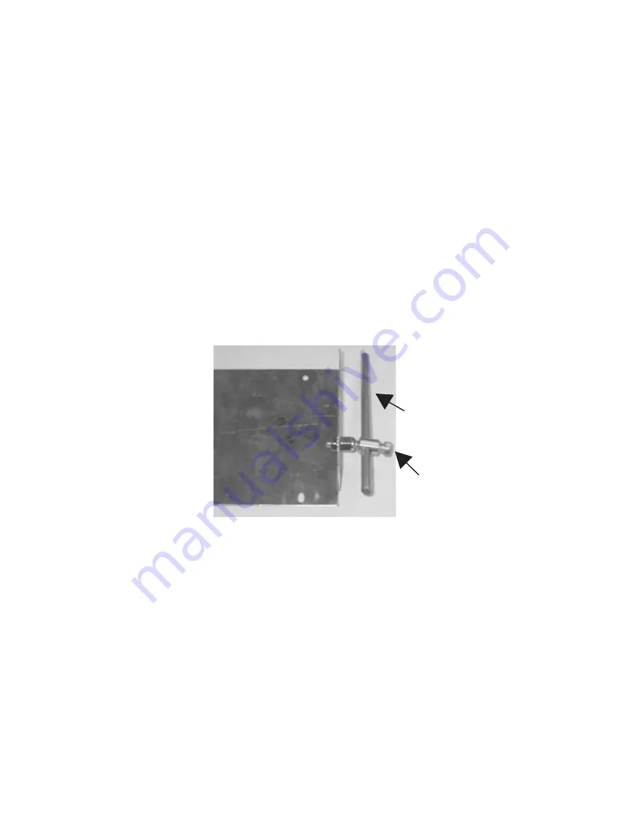
The amount of fresh air is determined by the position of the collar on the rod (

Figure 3

). To 

determine the desired quantity of fresh air:

  a.   With the indoor blower on, measure the quantity of supply air being discharged into the room with 

a balometer.

  b.  Now measure the quantity of the return air from the room. Subtract the return air from the supply 

air. The difference is the amount of fresh air.

  c.  Loosen the set screw that holds the collar onto the rod connected to the damper. Move the collar 

and tighten the set screw.

Rod

Set Screw

Figure 8 - Damper Adjustment

  d.  Repeat steps a, b and c until the desired amount of fresh air is being introduced into the room.
  

Important Note:

 Since Configuration Y does not have internal pressure relief, the fresh air must 

have a passage to the outside. If a passage is not available, the desired quantity of fresh air cannot 

be introduced into the room.

  Motorized Damper - 0 to 450 cfm of Outside Air and Pressure Relief (Configuration B) and 

the Manual Damper with Pressure Relief (Configuration Z).

 The settings of the damper require a 

balometer and a thermometer for measuring internal and external temperatures.
a.  Measure the total supply air with a balometer. If the supply air is controlled by a manual fan speed 

controller, make certain that the air flow is in accordance with Table 1, Air Flow (CFM) at Various 

Static Pressures. This CFM is referred to as "C" in the illustration and equation below.

Summary of Contents for Eubank EAA1020H

Page 1: ...ine which features and options this unit is equipped with INSTALLER Affix the instructions on the inside of the building adjacent to the thermostat END USER Retain this manual for future reference Hea...

Page 2: ...low these rules may result in death serious bodily harm property damage and damage to the equipment Important Safety Precautions 1 USE CARE when LIFTING or TRANSPORTING equipment 2 TRANSPORT the UNIT...

Page 3: ...ve 26 3 4 Ventilation System Set Up 28 Chapter 4 Troubleshooting 4 1 Overview 30 4 2 Failure Symptoms Guide 31 4 3 Compressor Troubleshooting 32 4 4 Electric Heat Control 33 Chapter 5 Electrical Schem...

Page 4: ...stat Connection Diagram 24 Figure 6 Temperature Sensor Wires Modulating HGR Valve 27 Figure 7 Desired Temperature Set Point Modulating HGR Valve 27 Figure 8 Damper Adjustment 28 Figure 9 Damper Air Pa...

Page 5: ...meet the various ventilation and cooling requirements For school classrooms models are available to comply with the ASHRAE 62 1999 standard Ventilation for Acceptable Indoor Air Quality Where cooling...

Page 6: ...ht Hand All 11 2 to 3 ton units 20 Filter Option A 2 Pleated MERV 8 AC HP C D MERV 11 High Filtration Package E MERV 13 High Filtration Package None Special 21 Corrosion Protection A Condenser Coil On...

Page 7: ...131 F 29 C 55 C An Optional FCC switch is required for the cooling Mode Heating mode ratings are 47 F Outdoor Temperature Performance loss realized below this rating point Table 5 Ambient Temperature...

Page 8: ...t add humidity to the classroom The operation of the HGR coil is controlled by a humidity controller If the humidity rises above the set point on the controller and the temperature in the classroom is...

Page 9: ...eld installed only Not generally recommended for use on scroll compressor Adjustable Outdoor Thermostat Will not allow electric resistance heat to be energized unless the outdoor temperature is below...

Page 10: ...able information to the end user Special features include 2 Stage operation with varying speed control to optimize latent and sensible capacity built in remote communication Modbus for monitoring and...

Page 11: ...Control Board Power Indicator LED 2 2 Installation and Replacement The PCB is factory installed To install a replacement PCB use the six mounting holes along with the appropriate screw size to firmly...

Page 12: ...delay in seconds 4 IBM Y1 Set 80 40 100 G Fan only and Y1 1st Stage Cooling Indoor Blower Speed Setting 5 IBM Y2 Set 100 40 100 Y2 2nd Stage Cooling Indoor Blower Speed Setting 6 OFM Select P P dC P P...

Page 13: ...orhigh pressurelockout 6 OFM Select This setting allows the IBM Indoor Blower control signal to be configured for PWM or 0 10vdc control The default control output signal is PWM 7 OFM Set This is an i...

Page 14: ...default to compressor cooling if any sensor becomes disconnected or faulty ChangingtheECONOSelecttoN no willdisableeconomizeroperationandtheeconomizer function will be ignored 13 SensorType Thissettin...

Page 15: ...are Version Number The software version of the 92589 control board will be displayed on the seven segment display This is for informational purposes only 2 4 Operation Power The Eubank PCB requires 24...

Page 16: ...ps 5 0 Dehumidification Operation AC HP 5 1 Hot Gas Reheat 5 2 Electric Reheat 6 0 Refrigeration Protection 6 1 High Pressure lockout 6 2 Low Pressure Lockout Freeze Protection 6 3 Anti Short Cycle 7...

Page 17: ...rity This means that in any combination involving the G input the speed associated to Fan Only will never take precedence The priority list from Highest to Lowest goes as follows 1 Y2 Request 2 Y1 Req...

Page 18: ...e switch reopens at 290 PSIG These outputs function as described until the Cooling setpoint is satisfied This is considered as ON OFF fan cycle control and the PSC motor will not modulate Note Single...

Page 19: ...ince Y2 has higher priority These outputs remain energized until the cooling setpoint is satisfied Once the setpoint is satisfied the Compressor and the Outdoor fan outputs are de energized The Indoor...

Page 20: ...e testing of the air conditioner at the factory the control board has been configured for the sensor type used in the system There should be no need to change the sensor configuration If an enthalpy s...

Page 21: ...rovides a signal to the economizer controller for modulating the position of the damper The default supply air temperature is 55F in economizer cooling and is not adjustable A disconnected or faulty s...

Page 22: ...e a defrost cycle based on the time selected in the control board configuration menu setting 8 The defrost time intervals selections are 30 60 and 90 minutes and the factory default setting is 30 minu...

Page 23: ...in off as long as the request for W2 is active Once the request for W2 satisfies the compressor will be allowed to operate The default setting for SCKT is N No the electric heat and compressor will be...

Page 24: ...ure of 80F and 115F Systems with PSC Outdoor Motors utilizes a Fan Cycle Switch which closes at 400 PSIG to energize the OFR outdoor fan relay to start the outdoor fan which runs until the switch reop...

Page 25: ...ng it from excessive short cycling When the compressor goes off due to any fault emergency or if the cooling heat pump heating setpoint is satisfied a built in 3 minute timer locks the compressor for...

Page 26: ...the system will operate in normal cooling mode until the request for FC is satisfied Once satisfied the system will be allowed to return to economizer operation if conditions are favorable 7 4 LowVol...

Page 27: ...for 24 hours with primary power turned on 2 Attempt to start the compressor after 24 hours 3 If the compressor will not start makes excessive noise or will not operate return the unit to the freight...

Page 28: ...learance From the Front Min Clearance Around Sides Single Unit Min Clearance Between Sides Two Units Min Space Above Unit EAA1020H 1024H EAA2024H 42 inches 30 inches 18 inches 24 inches EAA1030H 1036H...

Page 29: ...s chosen on the Heat Pump The humidity controller controls the heat pump system when cooling or heating requirements are satisfied and the need exists to dehumidify the conditioned space When cooling...

Page 30: ...all governmental authorities have jurisdiction The information contained in this manual is intended for use by a qualified service agency that is experienced in such work is familiar with all precaut...

Page 31: ...must be constructed of galvanized steel with a minimum thickness of 019 Ductwork must be firmly attached secured and sealed to prevent air leakage Do not use duct liner on inside of supply duct withi...

Page 32: ...his opening Allow sufficient clearance to run 3 4 conduit through the hole and to the unit 2 Apply a bead of silicone sealer on the wall side of the mounting brackets on the Heat Pump Circle the mount...

Page 33: ...lified persons CAUTION This Eubank Heat Pump may incorporate an internal crankcase heater for compressor protection The crankcase heater must be energized for at least 24 hours prior to starting the c...

Page 34: ...ompressors in the reversed direction for a short duration of time usually defined as less than one hour However after several minutes of operation the compressor s internal protector will trip The com...

Page 35: ...35 Eubank Wall Mount Heat Pump I O Manual 05 2023 Rev 2 Figure 5a Humidity Control Wiring Detail Heat Pumps Figure 5b Thermostat Connection Diagram...

Page 36: ...our heat pump 5 Removethecoverplatefromthethermostat Slowlylowerthethermostatcoolingsetpointtemperature Once the indoor fan turns on allow approximately three minutes for the compressor and outdoor fa...

Page 37: ...ycle on after time delay standard on Eubank heat pumps with an economizer and optional on all other Eubank units has cycled 3 Move the system switch to the Off position All functions should stop The B...

Page 38: ...F Insert the probes of the meter into the negative black and positive red set point test terminals on the board Carefully and in small increments turn the blue knob on the potentiometer until the vol...

Page 39: ...the return air from the supply air The difference is the amount of fresh air c Loosen the set screw that holds the collar onto the rod connected to the damper Move the collar and tighten the set screw...

Page 40: ...indoor air by B d Calculate what the Tmix should be with the desired quantity of outside air Measure the actual temperature of Tmix at the inlet to the supply air blower or at the inlet of the supply...

Page 41: ...e classroom using best industry standards and practices Adjust the speed of the intake air GreenWheel ERV blower until the required outside air is being brought into the classroom c Now measure the ex...

Page 42: ...ly after making this initial inspection The troubleshooting information in this manual is basic The troubleshooting section contains problem solution charts for general problems followed by a compress...

Page 43: ...ration 4 Check air filter s Check blower operation Remove airflow restriction C Unit cycles on high pressure or loss of charge 1 Loss or restriction of airflow 2 Restriction in refrigerant circuit 3 R...

Page 44: ...failures before condemning the compressor The following electrical tests will aid diagnosis on single phase units 1 Start Up Voltage Measure the voltage at the compressor contactor during start up Th...

Page 45: ...o the heater assembly the switch will have to be replaced by qualified service personnel after the source of the overheat problem is resolved In addition to the thermal cut out switch described above...

Page 46: ...is available The heater drives liquid refrigerant from the crankcase and prevents loss of lubrication caused be oil dilution Power must be applied to the unit for 24 hours before starting the compress...

Page 47: ...47 Eubank Wall Mount Heat Pump I O Manual 05 2023 Rev 2 Figure 11a Typical 1 Electrical Schematic Diagram Heat Pump Models EAA with Manual Outside Air Damper...

Page 48: ...48 Eubank Wall Mount Heat Pump I O Manual 05 2023 Rev 2 Figure 11b Typical 208 230v 3 Electrical Schematic Diagram Heat Pump Models EAA...

Page 49: ...49 Eubank Wall Mount Heat Pump I O Manual 05 2023 Rev 2 Figure 11c Typical 460v 3 Electrical Schematic Diagram Heat Pumps Models EAA with the PC Control Board...

Page 50: ...electrical components Be sure the unit has dried before restarting Use a fin comb of the correct spacing to straighten mashed or bent fins Outdoor Coil Periodically inspect the outdoor coil and the ca...

Page 51: ...er material charges 2 Damages caused by shipping accident abuse negligence misuse fire flood or Acts of God 3 Damages caused by operating or staging the unit in a corrosive environment 4 Damages cause...

Page 52: ...ply outlet duct flange on the unit The 1 25 4 mm clearance must extend on all sides of the supply duct for the first 3 feet 1 meter from the unit IMPORTANT Eubank requires a minimum of 1 25 4 mm from...

Page 53: ...r heaters 6 Install the two No 10 screws in the heater assembly plate 7 Install wire harness in hole provided in drain pan and then through filter bracket and then into control box 8 Wire the heater a...

Page 54: ...54 Eubank Wall Mount Heat Pump I O Manual 05 2023 Rev 2...

Page 55: ...________________________________________________ Compressor Serial No _________________________________________________________ D Pre Start Up Is there shipping damage Yes No If so describe __________...

Page 56: ...o full time operation Improper voltage can cause the compressor to overheat and cause premature failure Measured Line to Line Balance Is incoming voltage properly balanced use formula below to calcula...

Page 57: ...CHECK Incoming Power and Voltage Balance in Cooling Mode Measured Line to Line Volts L1 L2 _______V L1 L3 ________V L2 L3 ______V Is incoming voltage between Min and Max voltage listed on unit Data La...

Page 58: ...en installed wired to the Dehumidification input Yes No Has the Humidistat Control been properly setup for dehumidification Yes No Adjust the cooling setpoint so there is No demand for cooling Adjust...

Page 59: ...mizer Control Board been properly wired to the Control Yes No Has the Economizer Control Board Ambient selections been properly setup Yes No Has the Economizer Control Board Minimum Opening selection...

Page 60: ...Heating Heat Pump Check and Record Readings After about 10 minutes of operating in the heating mode check and record the following data points Inside Temperature IAT F Outside Temperature OAT F Enteri...

Page 61: ...rcuit Eubank Heat Pump control board must be set to Yes to allow Mechanical Heat Lockout Is the indoor blower motor IBM On Yes No Is the Compressor Off Yes No Is the Condenser Fan CFM Off Yes No Is th...

Page 62: ...uxiliary Heat or Mechanical Heat Lockout If you need assistance selecting the proper temperature contact tour HVAC system designer responsible for the application After adjusting the ODT for your appl...

Page 63: ...________________ ____________________________________________________________________________________ ____________________________________________________________________________________ _____________...

Reviews: