7
Eubank Wall Mount Heat Pump I&O Manual
05/2023 Rev.2
Model
Weight
Base
w/Economizer
w/3 Phase
w/Economizer & 3 Phase
EAA1020H/EAA1024H/EAA2024H
Lbs (Kg)
337 (153)
357 (162)
356 (161)
376 (171)
EAA1030H/EAA1036H/EAA2030H/EAA2036H
Lbs (Kg)
397 (180)
419 (190)
416 (189)
438 (199)
EAA1042H/EAA1048H/EAA2042H/EAA2048H
Lbs (Kg)
453 (205)
476 (216)
491 (223)
514 (233)
EAA1060H/EAA2060H
Lbs (Kg)
469 (213)
492 (223)
522 (237)
545 (247)
EGA1072H
Lbs (Kg)
576 (261)
599 (272)
629 (285)
652 (296
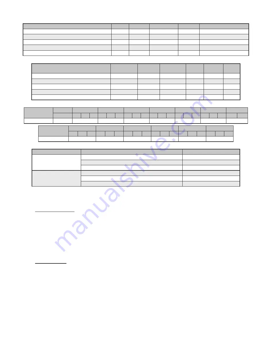
Table 2. Installed Weight (lbs (Kg)
Model
FILTER TYPE
INCHES
MILLIMETERS
PART
NUMBER
FILTERS
PER UNIT
MERV
RATING
EAA1020H/EAA1024H/EAA2024H
Return Air Filter 30 x 16 x 2 762 x 406 x 51
80138
1
8
EAA1030H/EAA1036H/EAA2030H/EAA2036H
Return Air Filter 36½ x 22 x 2 927 x 559 x 51
80162
1
8
EAA1042H/EAA1048H/EAA2042H/EAA2048H
Return Air Filter 36½ x 22 x 2 927 x 559 x 51
80162
1
8
EAA1060H/EAA2060H
Return Air Filter 18 x 24 x 1
457 x 610 x 25
81199
2
8
EGA1072H
Return Air Filter 18 x 24 x 2
457 x 610 x 51
81257
2
8
Table 3. Filter Size (inches)
Model
EAA1020H
EAA1024H
EAA1030H
EAA1036H
EAA1042H
EAA1048H
EAA1060H
EGA1072H
A
A
C
D
A
C
D
A
C
D
A
C
D
A
C
D
A
C
D
C
D
Charge Amount
100
110
114
130
185
185
185
210
Model
EAA2024H
EAA2030H
EAA2036H
EAA2042H
EAA2048H
EAA2060H
A
C
D
A
C
D
A
C
D
A
C
D
A
C
D
A
C
D
Charge Amount
120
120
150
185
185
220
Table 4. Refrigerant Charge (R410A, Ounces)
Basic Model
Special Option
TEMPERATURE RANGES
Non-Economizer
Base Unit
*20ºF - 131ºF (-7ºC - 55ºC)
Desert Duty
*20ºF - 131ºF (-7ºC - 55ºC)
Extreme Duty
*0ºF - 131ºF (-18ºC - 55ºC)
Economizer-Equipped
Base Unit
-40ºF - 131ºF (-29ºC - 55ºC)
Desert Duty
-40ºF - 131ºF (-29ºC - 55ºC)
Extreme Duty
-40ºF - 131ºF (-29ºC - 55ºC)
**An Optional FCC switch is required for the cooling Mode. Heating mode ratings are @47°F Outdoor Temperature. Performance loss
realized below this rating point.
Table 5. Ambient Temperature Operating Ranges
1.5 General Operation
Refrigerant Cycle
Eubank heat pumps use R-410A refrigerant in a conventional vapor-compression refrigeration cycle to
transfer heat. In the cooling mode, a double blower assembly blows indoor air across the evaporator (indoor
coil). Liquid refrigerant passing through the evaporator is boiled into gas by heat removed from the air.
The warmed refrigerant gas enters the compressor where its temperature and pressure are increased. The
hot refrigerant gas condenses to liquid as heat is transferred to outdoor air blown across the condenser
(outdoor coil) by the condenser fan. Liquid refrigerant is metered into the evaporator through a metering
device to repeat the cycle. In the heating mode, the process is reversed.
Heating Mode
During heating mode a special reversing valve reverses the flow of refrigerant through the system
exchanging the roles of the condenser and evaporator. Now the outdoor coil becomes the evaporator and
the indoor coil becomes the condenser. The refrigerant then flows through the outdoor coil, picks up heat
and becomes vaporized. The vapor then enters the compressor where it is compressed to a higher pressure
and temperature. Next it is pumped to the indoor coil where the heat will be released into the room. The
compressed refrigerant vapor will condense to its liquid state as it gives up heat. Finally, liquid flows
through a metering device into the evaporator where the cycle will be repeated.
Optional electric strip heat is available for all models. Please see Appendix A for instructions on field
installation of electric heat.


