47
S/N
Failure
Code
Symptom
Possible Cause
Solution
18
The LED indicator
of the unit displays
ER34 and the
wired controller
displays 34
System 2 suction
temperature is too
high (40°C)
1. Four-way valve jammed.
Gently knock the sides of the four-way valve
and restart the system. Should the alarm
persist, replace the four-way valve.
2. Incorrect coil operation of the four-way
valve.
Replace the coil.
3. Compressor idle protection due to air
discharge temperature is too high.
Refer to item 19 in the table.
19
The LED indicator
of the unit displays
ER35 and the
wired controller
displays 35
System 2 discharge
temperature is too
high
1. Damaged fan motor (cooling).
Check and troubleshoot accordingly.
Recover and recharge accordingly.
2. Air circulation short circuited (cooling).
3. Heat exchanger is dirty (cooling).
4. The electronic expansion valve is not
opened as expected (heating).
Check the electronic expansion valve and
troubleshoot accordingly.
5. Water temperature is too high.
Insufficient refrigerant or leakages.
Change the setting for return water temperature
(to be performed by service personnel).
6.
7. Incomplete defrosting.
Change the defrosting parameter to be
performed by service personnel
20
The LED indicator
of the unit displays
ER36 and the
wired controller
displays 36
System 1 low
pressure
1. Poor heat exchanging performance
(heating).
Check the outdoor unit and troubleshoot
accordingly.
2. Outdoor fan motor have abnormality
(heating).
Check and troubleshoot accordingly.
Check for leakages.
Recover and recharge if needed.
System is leaking refrigerant or
insufficient.
3.
4. Low pressure input port faulty.
Replace the module.
5. Low pressure sensor damaged.
Replace the pressure sensor.
21
The LED indicator
of the unit displays
ER37 and the
wired controller
displays 37
System 1 suction
superheat is too low
1. Low pressure or temperature sensor
is faulty
Check and replace if needed.
2. Electronic expansion valve control
algorithm malfunctioned.
Update the module
22
The LED indicator
of the unit displays
ER38 and the
wired controller
displays 38
System 1 leaking
refrigerant
1. Low pressure sensor failed.
Check and replace the sensor if needed.
Recover and recharge accordingly.
2. Insufficient refrigerant charged.
23
The LED indicator
of the unit displays
ER39 and the
wired controller
displays 39
System 2 leaking
refrigerant
1. Low pressure sensor failed.
Insufficient refrigerant charged.
Check and replace the sensor if needed.
Recover and recharge accordingly.
2.
24
The LED indicator
of the unit displays
ER40 and the
wired controller
displays 40
System 1 discharge
temperature sensor
failed
1. TH1 temperature sensor is loosen or
broken off.
Check the control module and ensure the
sensor is securely connected.
2. TH1 temperature sensor is shorted/
open.
Check whether the resistance of TH1
sensor meets specification requirements/
replace if not.
3. Detection circuit for the temperature
sensor in the control module has
malfunctioned.
Replace the control module.
25
The LED indicator
of the unit displays
ER41 and the
wired controller
displays 41
System 2 discharge
temperature sensor
failed
1. TH2 temperature sensor is loosen
or broken off.
Check the control module and replug the
temperature sensor.
2. TH2 temperature sensor is shorted/
open.
Check whether the resistance of TH1
sensor meets specification requirements/
replace if not.
3. Detection circuit for the temperature
sensor in the control module has
malfunctioned.
Replace the control module.
Summary of Contents for A5MAC 210D
Page 1: ...Technical Manual AIR COOLED MODULAR CHILLER A5MAC 210D A5MAC 230D A5MAC 340D A5MAC 450D...
Page 14: ...14 Wiring Diagrams MODEL A5MAC210 230D...
Page 15: ...16 1 4 5 3 2 7 8 6 1 4 5 3 2 7 8 6 A5MAC340DR...
Page 16: ...17 1 4 5 3 2 7 8 6 1 4 5 3 2 7 8 6 A5MAC450D...
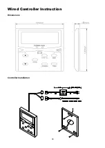
Page 36: ...38 Wired Controller Instruction Dimensions Controller Installation...


