6
servos), your elevator/rudder mixing will still be able to function correctly. Similarly, if you wish to
connect your gyro to the ailerons (each operated by its own servo), the gyro will not affect your mix.
Your
FUZZY SMM
has a third input for gain control which allows you to you adjust the sensitivity or
effectiveness of the gyro, and you can do it while in flight. This requires an adjustable control knob or a
pot on your transmitter (or a programmable mix if you have a computer radio). You may also turn the
gyro off when it is not needed.
A built-in and adjustable mixer reduces the gyro’s effect when you move the control stick from center,
you have the same feel or responsiveness that you would without a gyro—a kind of reverse
exponential effect. In addition, the gyro recognizes when the input is coming from the stick or from a
mix. For example, if you are using your gyro to stabilize your ailerons and you have a flaperon mix, the
gyro’s sensitivity will not be reduced when the ailerons are extended by your flaperon mix.
Mode I (Standard)
Works like all former gyros as a dampener, useful for all manoeuvers.
Mode II HEADING/AVCS
New gyro characteristics. Holds the position or direction of the model arround the stabilized axis until a
given stick control.
Adjustments
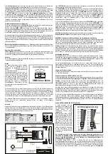
Function of DIP-Switches
ON OFF
1
Servo 1 direction Normal
Servo 1 direction reversed
2
Heading Mode
Normal Mode
3
Set Servo limit
Normal-use
4
Servo 2 direction Normal
Servo 2 direction reversed
Every change of DIP-Switch need a certain waiting in OFF position of receiver until the change
will be recognized. IMPORTANT
: After switching the receiver ON,
DO NOT move the model for
about 3-5 seconds, until the Led flashes
. During this time the gyro calibrates the piezo sensor´s
centre position, and confirms that the unit is functioning correctly - indicated by the LED flashing.
DIP switch 3:SET LIMITS
With that switch in ON position during switching-ON procedure for receiver, the servo end position
adjustment starts. Use full servo throw. Use the tail rotor stick and move it slowly to one end position,
back to centre and to the other end position. Now the Gyro knows the stick throw and the centre
position used. We recommend that this centre position is hover-position. Now switch the DIP switch 1
back to OFF position, the servo moves to left, centre and right position to indicate the stored positions.
Switch OFF receiver, wait 10 seconds ore more and switch ON receiver again. The gyro knows now
the positions and the tail servo will never move over these positions during flight. Please take care that
with these end positions no mechanical limit from the linkage to the servo can happen.
DIP switch 1+4: Servo reverse
With these DIP switches the servo direction can be reversed. It reverses the servos direction for control
movements of the servos, given from the gyro (not from transmitter controls).
DIP switch 2: MODE II HEADING/AVCS
In OFF position (MODE I) the gyro is a Standard gyro, in ON position the gyro works in two modes,
depending to the position of the gain channel. Minimum gain is in the centre (1,5ms) of the gain
channel. Maximum gain for either Standard-Mode (MODE I) or HEADING Mode (MODE II) is at the
end positions of the gain channel. As indication, the LED flashes 2 x at NORMAL, 3 x MODE II. In
HEADING mode, the gyro holds the position/direction of the stanilized axis, as long as there is no stick
control from the pilot. The position is set either when switching ON receiver in HEADING mode,
switching from Standard- to HEADING-Mode or after every stick control movement.
Pot 1, "Dynamic" Pot Adjustment
The best gyro results can be reached wíth with the maximum possible sensiitivity. With the "Dynamic"
pot, the gyro´s response in MODE I and Mode 2 can be tuned to your model´s characteristics. Every
model has different servo speeds, controls aso., so the dynamic pot can be adjusted to change the
response curve in relation to the rate of turn. The better the dynamic is adjusted, the higher the
sensitivity can be adjusted. Please adjust the pot with a small pozi-drive screwdriver. Left position =
soft dynamic, right position = hard dynamic. If the model starts to wag out, reduce dynamic pot position
to soft direction and try to increase sensitivity (gain) again.
If the gain-channel of the FUZZY SMM is not connected to the receiver, the pot works as manually gain
pot, the gain can be manually adjusted here.
Pot 2, Stick fade out adjustment
A built-in and adjustable mixer reduces the gyro’s effect when you move the control stick from center,
you have the same feel or responsiveness that you would without a gyro—a kind of reverse
exponential effect. The pot adjusts the point, were the gyro will be switched of when you move the
control stick at the transmitter. The adjustment effects with a small delay.
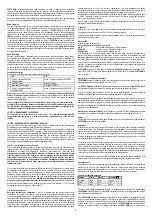
LED Status
LED-Indication, Voltage control
X-X-X
Mode Normal, gain manually adjusted
XX-XX-XX
Mode
I,
Normal
XXX-XXX-XXX
Mode II, Heding
Installing the
Fuzzy SMM
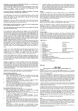
The sensor must be installed in a way, that it’s
axis
and the wanted axis of the model are identical (
s.
picture). The
sensor-axis
works from
above t
hrough the
sensor-case
. The installation in the model
must occur from the ground of the
sensor case
being mounted exactly to the desired axis. We
recommend the fixing of the sensor with enclosed
double adhesive tape
. Stick the
top-sensor
into the
planned place in the mechanics. The experience shows that the
top sensor
should be mounted if
possible at a place in the model far away from an engine, since the
sensor element
even measures
engine vibration
as movement and passes it to the servo. This can lead to considerable
servo
problems.
The used servo is headed by the high
decomposition o
f the sensor very frequently, which
can lead to higher
servo wear
. The best
top result
is achieved of course with fast servos.
The
electronics-case
of the gyro can be installed at a suitable place in the model, packed in foam
rubber.
Connection:
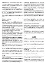
The connectors on the
FUZZY SMM
use the Futaba polarity system. Therefore any Futaba, JR or
Hitec equipment is directly compatible with the unit.
Lead colours :
System
Plus (+)
Minus (-)
Signal
Graupner/JR red brown
orange
Futaba red
black white
MPX
red
black
yellow
The gyro is connected between the receiver and the servo for the deisred control. The connector
without a mark is plugged into the receiver output for the servo. The lead with the mark is connected to
the Gain (AUX) channel on the receiver. The Gain channel should correspond to a free proportional
channel on the transmitter, so that the gain can be easily adjusted in flight.
Practice
Adjustment of Gyro Direction
Before connecting the gyro, please make sure that the control of the model you want to stabilize is
responding in the correct direction to the movement of the transmitter stick. Then connect the gyro to
the receiver and servo as described above and set the gyro gain (AUX) on the transmitter to 100%
(only for test purpose, we test on aileron).
Hold your model and quickly rotate it about the axis the gyro is operating. In the case of our example
for the roll axis, quickly bank the model to the right and the left as if it was performing a roll. When the
right wing dips downward, observe which way the right aileron responds. If installed correctly, the right
aileron should deflect downward to counteract the right roll of the model. Similarly, when the left wing
moves upward (as if in a right bank), the left aileron should deflect upward to counteract the right roll of
the model. If your gyro responds opposite of the way described, turn the receiver switch off and
reverse the DIPswitches on the gyro. Turn the receiver switch back on and test again.
CAUTION:
If the gyro direction is set incorrectly, the model can’t be controlled anymore durcing flight.
If everything is installed correctly and checked, then the gyro gain should be set to about 30% for the
first flights.
Operation MODE I (DIP-Switch 2 in Position OFF)
The gyro gain is controlled directly from the transmitter (AUX channel), and can be adjusted from 0% to
100% gain. However for the first flight we recommend starting with about 30%-40% gain. Once in the
air, increase the gain slowly until the model starts to wag out, then reduce the gain until it stops.
If you are experienced with that function, you can adjust the dynamic pot and try to increase the gain.
Operation MODE II, HEADING (DIP-Switch 2 in Position ON)
If the gyro shall be used in HEADING, set DIP switch 3 in position ON. With this MODE the gyro offers
both Modes, Standard- and HEADING-Mode. In HEADING-Mode the gyro holds the position of the
stabilised axis as long as the stick is in centre position. During stick movement, the gyro has no
function, the stick is directly working with the controls, after the stick has reached the centre position
again, the gyro recognises the last position of the model as its new position to hold on. In MODE II the
AUX channel changes as shown. Minimum sensitivity is in 0-position, maximum sensitivity in Standard-
Mode is at one max. position of the sensitivity channel, max. sensitivity of HEADING-Mode is at the
other end of the sensitivity channel. In that way it can be switched between Standard-Mode and
HEADING-Mode. HEADING will be indicated with LED twinkling 3 times.
In HEADING it also should be started with 30%-40% sensitivity. Once in the air, increase the gain
slowly until the model starts to wag out, then reduce the gain until it stops. If you are experienced with
that function, you can adjust the dynamic pot and try to increase the gain.
During HEADING, you can say there is no stick trimm available, because a given trimm amount will
lead to a a turn of the model. Therefore trim the model during use of Standard-Mode, then switch to
HEADING. The trim position of Standard-Mode will be overtaken to zero position of the tail during
HEADING. Any further trim movement during HEADING will start to turn the helicopters tail.
In HEADING-Mode, the gyro controls the angle speed in conjunction to the stick position, therefore any
servo signal out of the centre position will result in turning the model.
Note:
A slow drifting of the servo’s neutral position during HEADING is normal. During use it will be
compensated.
Technical data’s
•
Voltage range
3,3 Volt - 9 Volt
•
Consumption
about
45
mA
•
Weight
about
30
Grams
•
Size
48 x 39 x 15 mm
•
Temperature
range
-10° - +50° Celsius
•
Servo-limiter by Software
•
3-level, self learning temperature drift compensation
•
NORMAL/REVERSE-Switch
•
8-Bit Microprocessor, Clock speed 22 MHz, 4096 Bit
•
Programmable Servo throw and centre position
•
Adjustable dynamic without PC
•
LOCK-ON-Function (Heading Lock) indicated by LED
•
Low voltage drop compensation for max. 2 seconds, no problem with switching ON procedure
•
LED-Monitor
We wish you much fun with the
FUZZY SMM
and a lot of more performance for your airplanes.


