2
cycles themselves, are set during start-up of system. The controller has 16 preset on
and off interval settings ranging from 3 to 48 doses per day. The zone dosing time can
be set from 6 minutes to 16 minutes. This allows the operator to closely approximate
the design loading rate. The dual alternating pump control panel ensures that both
pumps get equivalent use. The control panel allows both pumps to operate
simultaneously only during field flush cycle, when a larger volume of flow (velocity) is
needed to friction-scour the interior of all piping.
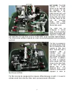
Disc Filtration --All suspended solids larger than 100 micron in size are filtered out of the
effluent stream before entering the driplines. For this purpose,
“
ACT
WFS
” uses an
appropriately sized disc filter battery; each filter element has a stack of serrated plastic
rings that provide length, width and depth for solids removal.
The plastic discs are permanent, and the automatic back flush is triggered by either a
pre-set time interval and/or pressure drop across the filters (say, > 6 PSI). Back flushed
liquids and solids are returned upstream to the primary treatment process (if nearby) or
to an adjacent back flush tank for settling.
Flow meter --Placed in-line downstream from the filters, the flow meter allows the
operator to monitor both instantaneous and daily flows.
Solenoid Valves --The "workhorses" of the pump station are the solenoid valves
controlling direction of the flow at pump start. During back flushing, filter valves are
closed sequentially to back flush each element, and the master valve is closed to
concentrate all flow to the specific filter element being back flushed.
Drain field Equipment and Operation
Equipment in the irrigated zones includes 1/2" diameter drip tubing buried 6-12" below
grade, PVC supply and return headers and mains, one electric solenoid valve per drip
field zone and a return main valve for monthly field flushing.
Drip Tubing -- The standard emitter used by
“ACT WFS” discharge 0.61 gph over the
pressure range of 7-70 PSI in the drip lines. Precise emission over a wide pressure
range allows much greater uniformity of subsoil wetting than is otherwise possible. Drip
lines are typically laid on 2’ centers, with a 24" spacing between emitters inside the
tubing. The pressure-compensating diaphragm within each emitter accomplishes
emission uniformity and functions as a self-cleaning mechanism. Other emitter flow
rates are available and include 0.42 gph and 0.92 gph.
PVC Mains -- Effluent is transported from the pump station via supply mains of
Schedule 40 PVC pipe. Tees and adapters are inserted at specified intervals within
each zone’s supply header for effluent feed into each drip line. At the end of each drip
line run, adapters and tees are again inserted to connect drip tubing to the return
header, creating a circular system for periodic field flushing of all mains, headers and
drip tubing in the system.
Field Solenoid Valving -- The drain field to be used for effluent disposal is divided into a
number of zones which are dosed one at a time and sequentially.


