background image

Unit 8 IDA Business Park, Whitestown, Tallaght, Dublin 24, Ireland. 

Telephone: 353 1 462 2585.  Telefax: 353 1 462 2587.  E-mail: sales@accesscontrol.ie   Web: www.accesscontrol.ie

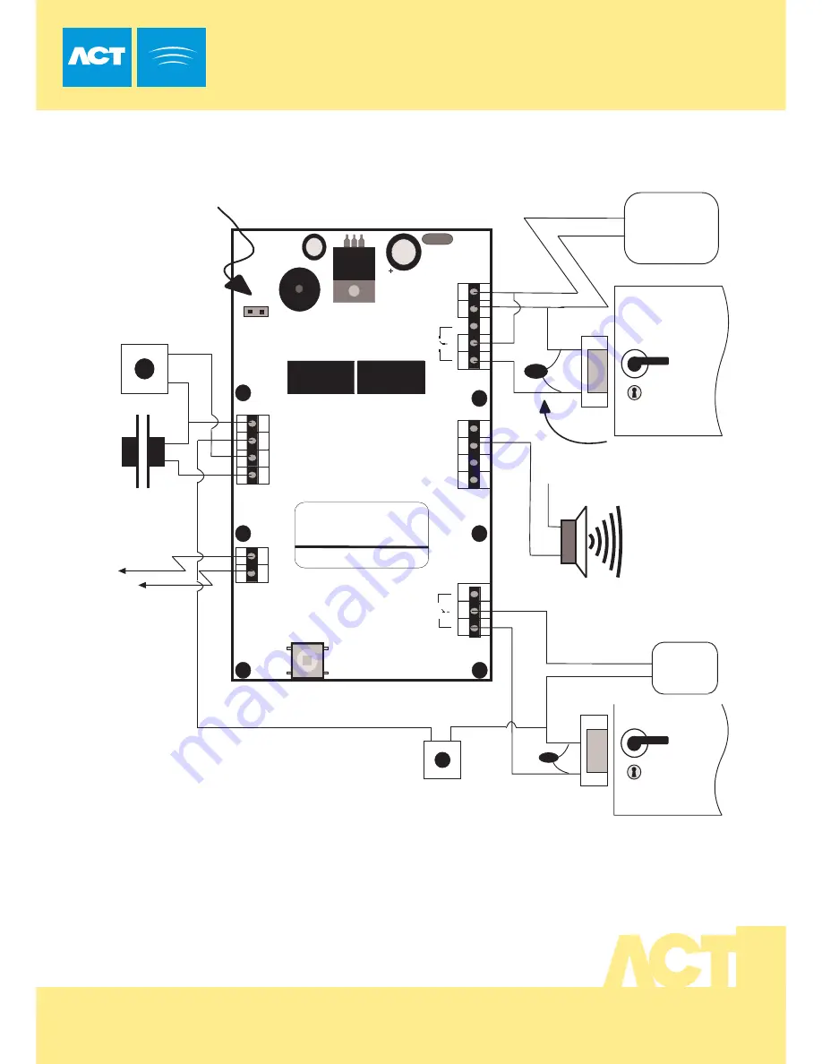
Typical ACT10 Configuration

(Normally de-energised lock shown)   

!


O M R O N

5 A

 2 5 0 V A C

5 A

 3 0 V DC

  0123456789


Important 

Always Place Varistor

Across All Lock Terminals

+V

Power up without link if

Programming code has been lost.

   +V

0V

Volt - Free

Tamper Contacts

Door Contact

Door Release 

Button

Guest Buzzer

Power Supply

12-24V ACDC

This diagram shows revision (3.1) of the ACT10 

This unit may be used to control 2 doors as illustrated in the 

diagram above.

Connections and programming for this unit are exactly the 

same as for previous versions, however the connector

positions have changed as shown in the above diagram.

  1

2-2

4

A

C

/D

C

-

+

N/C

N/O

C

0V

Buzzer

OP3

Duress

OP2

Interlock

O

U

TP

U

TS

IN

PU

TS

0V

Interlock

(PB2)

Push
Door 

Contact

Button

TA

M

PE

R

LK1

Serial No. 12345

Batch: 20xx-1

Product:ACT10 Rev3.0

N/C

N/O

C

   +V

0V

Door Release Button 

for Door 2

R

EL

A

Y

D

O

O

R

 2

O M R O N

5 A

  2 5 0 V

A C

5 A  3 0 V DC

Door 2

12-24V ACDC

Power Supply

Summary of Contents for ACT10 DIGITAL KEYPAD

Page 1: ...res of the keypad please refer to the complete programming guide on the other side of this sheet IMPORTANT As with any access control system always ensure that there is an alternate means of escape in the event of the unit failing to operate due to power loss or in the event of fire Unit 8 IDA Business Park Whitestown Dublin 24 Ireland Tel 353 1 4622585 Fax 353 1 4622587 Copyright 1999 Access Cont...

Page 2: ...tivated for the duration programmed in the guest buzzer timer 45 Fire Alarm Override When set the relay is held active whenever the interlock input is ac tive and the green indicator will flash This is useful for following a fire alarm system to override controlled doors 46 Release Button for Second door When set The keypad activates the door 2 relay which follows output 2 s timer this allows twod...

Page 3: ... Release Button Guest Buzzer Power Supply 12 24V ACDC This diagram shows revision 3 1 of the ACT10 This unit may be used to control 2 doors as illustrated in the diagram above Connections and programming for this unit are exactly the same as for previous versions however the connector positions have changed as shown in the above diagram 12 24 AC DC N C N O C 0V Buzzer OP3 Duress OP2 Interlock OUTP...

Page 4: ...s this will block the air vents and trap any water which may enter the keypad If a weather cowl is fitted the same applies Do install a weather cowl when the keypad is installed on an uneven surface or if in a very exposed area Do apply silicone to the top and two sides of the keypad or cowl when used Do silicone all screw mounting positions and cable entry ...

Reviews: