background image

10

Unpacking the device

Packing material

Please keep the original packing material. It is
designed for reuse (unless it is damaged in tran-
sit). Using the original packing material is the
only way to reliably protect the device during
transit.

Checking the package contents

Your OLS-6 is shipped with the following acces-
sories:

Belt carrying bag

Manual

Calibration certificate

Checking for damages in transit

After you unpack the device, check to see whe-
ther it was damaged in transit. This is particularly
likely if the packaging is clearly damaged. If
there is damage, do not attempt to operate the
device. Doing so can cause further damage.

Recovery following storage and transport

Condensation can occur if a device that is stored
or transported at a low temperature is brought
into a warm room. To avoid damages, wait until
no more condensation is visible on the surface
before powering up the device. Do not operate
the device until it has reached its guaranteed
temperature range (-10 to +55 °C).

Summary of Contents for BN 2255/02

Page 1: ...OLS 6 FC PC OLS 6 FC APC OLS 6 SC PC OLS 6 SC APC Optical Laser Sources BN 2255 02 BN 2255 21 BN 2255 45 BN 2255 46 Series P Operating Manual ...

Page 2: ...zations Without written permission of the ITU T and or ETSI it is not permitted to copy ITU T Recommendations or ETSI standards or parts thereof and or make them available to third parties Acterna Eningen GmbH Mühleweg 5 72800 Eningen u A Order no BN 2255 98 22 Edition 03 02 01 P Previous edition 02 00 09 P Note Specifications terms and conditions are subject to change without prior notice Copyrig...

Page 3: ...11 Control and display elements 12 Connecting test cables 14 Powering the device on and off 15 Selecting the wavelength 17 Selecting the signal type 18 Avoiding contamination 19 Battery charge status 20 Changing the batteries 21 NiCd cells 23 Cleaning the source output 24 Service information 28 Specifications 29 Device versions accessories 31 ...

Page 4: ...Contents 2 ...

Page 5: ...losses of fiber links and components most of which use 9 125 µm fibers A power meter is required to make these measurements We recommend the OLP 6 from Acterna In addition to its unmodulated light mode the OLS 6 also has three modulation frequencies for identifying fibers in a fiber bundle for example Features The OLS 6 comes in four different variants Variant Order number OLS 6 FC PC BN 2255 02 O...

Page 6: ...10 nm and 1550 nm The high output level 7 dBm is internally stabilized The lasers can be activated singly or simulta neously Dual mode As an independent function a modulation frequency of 270 Hz 1 kHz or 2 kHz can be selected Two other modes are also available Unmodulated light and Auto λ The latter function indicates the current wavelength to a power meter from Acterna e g OLP 6 8 15 16 18 OLS 6 ...

Page 7: ...w access to the display and keypad on the front side and the battery compartment on the back side The serial number is also found on the back side System connection using adapter cables Suitable adapter cables are available for all OLS 6 variants for all jack types If your OLS 6 is fitted with the same type of jacks as your power meter then you need an adapter cable with the same connector types e...

Page 8: ...6 Connector cables For details on test cables and FO couplers see the separate data sheet Optical Test Adapters and Adapter Cables ...

Page 9: ...r the purposes for which it was designed For more information see section Applications or page 30 Notice Non compliant usage can be hazardous to the user and or damage the device itself Þ Please make sure the allowable ambient conditions are not violated Checking the device prior to power on Þ Before powering up the device always make sure that it is in proper working order For more information se...

Page 10: ...n cause irreparable damage to the retina if you do not exercise caution Þ When the device is switched on never look directly into the output or into a connected optical fiber Always close the cables in order to protect other persons from ac cidental exposure Þ The laser source should be acti vated only if the test connection to the power meter has been made Þ Always switch off the device prior to ...

Page 11: ...9 Laser class Laser class ...

Page 12: ...s in transit After you unpack the device check to see whe ther it was damaged in transit This is particularly likely if the packaging is clearly damaged If there is damage do not attempt to operate the device Doing so can cause further damage Recovery following storage and transport Condensation can occur if a device that is stored or transported at a low temperature is brought into a warm room To...

Page 13: ... or NiCd cells Two 1 5 V dry batteries Mignon AA size Two 1 2 V NiCd cells Mignon AA size The typical operating life depends on the device version as well as the cell type For a clear li sting see section Power supply page 30 Þ Inserting the dry batteries NiCd cells For more information see section Changing the batteries or NiCd cells page 21 ...

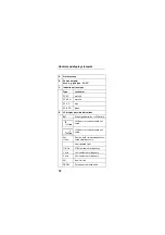
Page 14: ...C green D LC display possible indications BAT Discharged batteries or NiCd cells 1310 nm source wavelength acti vated 1550 nm source wavelength acti vated ALL 1 sec Dual mode Both wavelengths acti vated simultaneously Unmodulated light 270 Hz 270 Hz modulation frequency 1 kHz 1 kHz modulation frequency 2 kHz 2 kHz modulation frequency AU Auto λ mode PERM Permanent operating mode ...

Page 15: ...hes the device on and off Short keypress Brief operating mode Long keypress 2 sec Perma nent operating mode Selecting the source wavelength or setting Dual mode Switching from unmodulated light to the various modulation frequen cies and Auto λ mode ...

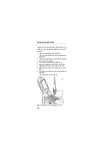
Page 16: ...e source outputs un derneath 2 Remove the protective cap from the connec tor on the test cable A 3 Clean the test cable see page 24 ff 4 Insert the ferrule C into the jack D You might need to turn the connector a little 5 Make sure the ferrule is all the way in the jack 6 Screw on the sleeve nut B in the clockwise direction The connection is now ready Figure OLS 6 FC PC jack type FC PC ...

Page 17: ... indicated by a brief flashing of all display elements and display of the percent battery ca pacity remaining Afterwards the most recent device settings are restored and displayed Your OLS 6 is now ready to transmit Brief operating mode Þ Press the ON OFF key briefly The OLS 6 powers on The device is ready to transmit as soon as the previous settings appear wavelength perhaps the modulation freque...

Page 18: ... or Wait until the device powers off automatically after 20 minutes Permanent operating mode Þ Press the ON OFF key for about two sec onds The OLS 6 powers on and now transmits in permanent operating mode This is indicated by the PERM indicator Power off Þ Press the ON OFF key The OLS 6 powers off ...

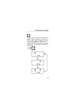
Page 19: ...ey to select individual wave lengths or the Dual mode ALL Circular func tion In single wavelength mode you can select from two switch positions 1310 nm and 1550 nm 780 nm and 1300 nm The third position ALL activates both wavelengths si multaneously ...

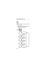
Page 20: ...18 Selecting the signal type Use the MODE key to select one of the five fol lowing signal types Unmodulated light CW continuous wave Modulated with a frequency of 270 Hz 1 kHz or 2 kHz Auto λ ...

Page 21: ...accuracy insertion loss reflec tion This can also cause permanent damage such as scratches on the optical surfaces This applies to the connectors on your OLS 6 and also to the connectors on the test cables Tip Þ Clean the connectors on your test cables be fore connecting them by wiping off the sur face with a piece of cleaning strip Þ When you take a break always close the protective cap if you re...

Page 22: ... dry batteries but a maximum value of only about 60 is displayed for freshly charged NiCd cells Discharged batteries or NiCd cells When the batteries or NiCd cells start to run low the BAT indicator appears From this point on you have about two hours left to go if you are us ing dry batteries Once this remaining operating life elapses the display switches off except for the BAT indicator After abo...

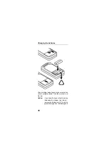
Page 23: ...d cells You can access the battery compartment even when the shock protector is installed Change the batteries as shown in the drawing Tip Please do not throw used batteries or NiCd cells into your normal trash since they can contain poisonous heavy metals In many countries nowadays you can dispose of used batteries or NiCd cells at special waste gathering centers ...

Page 24: ... batteries make sure that the cover is properly closed The slide must lock in at the top Notice If you know that you will not be using the device for a longer time interval remove the batteries or NiCd cells to prevent damage due to bleeding cells ...

Page 25: ...ls Tip Store the NiCd cells in a cool but frost free dry room to hinder their natural discharging effects The natural discharging effects become more prevalent as the cells age Tip You should always recharge fully discharged cells immediately since over a longer period of time the natural discharging effects can damage the cells due to deep discharge Tip If you have an intelligent charger with a d...

Page 26: ...e radiation can cause irrepara ble damage to the retina if you do not exercise caution Þ To inspect or clean the source outputs always power down the device be forehand or take out the bat teries Caution Break in fiber The fiber can break if you pull it out too far during cleaning or bend it too much Note that the guarantee does NOT cover this sort of damage Þ Please pay close attention to the fol...

Page 27: ...cks Notice Never loosen both jacks at once since the two fiber windings inside the device can become displaced They might then be damaged when you replace the jacks 1 Loosen the screws that hold the output jacks in place Tip Put the screws in a safe place 2 Carefully pull out the jack up to as far as the front inside edge of the unfolded protective cap ...

Page 28: ...ec tor Do not twist the fiber 4 Pull out the jack from the internal ferrule The fiber end surface is now easily accessible Cleaning the fiber end surface 1 Taking into account the relevant safety pre cautions you can now examine the connec tor with a suitable microscope 2 If it is very dirty lightly apply a cleaning strip e g Scotch Magic tape to the end sur faces and pull it off again ...

Page 29: ... end surface of the ferrule 4 Now wipe again with a dry lint free paper tis sue Cleaning the jack 1 If the jack is very dirty clean it with a suitable tool 2 Blow out the loosened jack with clean pres surized air from a can anti dust spray Þ Now reverse the order and reconnect the jack with the internal fiber and install it ...

Page 30: ...f test Possible error messages 1 Acknowledge the error message by pressing any key 2 Power off the device 3 Contact your nearest Acterna Service Cen ter See the inside cover for the address Code Meaning E2 An error occurred in the program memory This can cause malfunctions in keypad operation or cause the device to lock up E3 A checksum error occurred in the calibra tion data memory A functional i...

Page 31: ...PC 2 x SC APC Output power level1 Unmodulated light mode CW 7 dBm typ 1 dB Modulated typ 10 dBm 1 Reference condition 9 125 µm fiber 23 C 3 C Power level stability Short term stability after 30 min 15 min 10 C to 55 C T 3 C 0 02 dB Long term stability after 15 min 8 h 10 to 55 C T 3 C 0 02 dB Modulation Modulation frequencies 270 Hz 1 kHz 2 kHz Waveform Squarewave 1 1 Modulation factor 100 Modulat...

Page 32: ...2 x Mignon AA 1 5 V NiCd cells 2 x Mignon AA 1 2 V Operating life1 2 Batteries NiCd cells typ 60 h 20 h 1 Dual mode frequency modulated 2 Automatic power off after approx 20 min to save battery life function is disabled in PERM mode Dimensions and weight Weight w batteries approx 200 g Dimensions w x h x d in mm 73 x 28 x 140 Electromagnetic compatibility EMC as per EN 50 082 1 and EN 50082 1 CE c...

Page 33: ... Charger for external charging 220 V European connector 110 V US connector BN 2229 90 03 BN 2229 90 09 Cleaning strip for optical connectors BN 2229 90 07 OMK 6 complete set BN 2126 06 MK 5 Test Kit room for 2 devices and accessories BN 2126 90 01 MT 32 Test Kit room for 3 devices BN 2126 32 1 See also page 5 For more information on test cables and FO couplers see the separate data sheet Optical T...

Page 34: ...32 Device versions accessories Notes ...

Page 35: ...nhances cooperation between ourselves and our business partners The Acterna Environmental Management Program considers Product design and manufacture Environmental restrictions and requirements are taken into account during planning and manufacture of Acterna pro ducts This attention ranges form the raw materials and finished components selected for use and the manufacturing processes employed thr...

Page 36: ... Our customers in Germany can already take advantage of our return service for used instruments In Europe all new equipment purchased from Acterna can be returned for scrapping at the end of its useful life free of charge If you would like specific information about the Acterna Environmental Management Program please contact us at Germany Environmental Management Tel 49 0 7121 86 1470 Fax 49 0 712...

Page 37: ...Av Eng Luis Carlos Berrini 936 8o e 9o andares 04571 000 São Paulo SP Brasil Tel 55 11 5503 3800 Fax 55 11 5505 1598 Asia Pacific 42 Clarendon Street PO Box 141 South Melbourne Victoria 3205 Australia Tel 61 3 9690 6700 Fax 61 3 9690 6750 Western Europe Arbachtalstraße 6 72800 Eningen u A Germany Tel 49 7121 86 2222 Fax 49 7121 86 1222 Eastern Europe Middle East Africa Elisabethstrasse 36 PO Box 1...

Page 38: ......

Page 39: ...ABC ddd 37 Figure OLS 6 FC PC jack type FC PC For comments see page 12 ff ...

Page 40: ...ABC ddd 38 ...

Reviews: