background image

www.acti.com


Hardware Manual 


42


Use the default IP address of the camera 

If there is no DHCP server in the given network, the user may have to manually assign the IP 

addresses to both the PC and the camera to make sure they are in the same network 

segment. 


When the camera is plugged into the network and it does not detect any DHCP services, it will 

automatically assign itself a default IP: 


192.168.0.100 


Whereas the default port number would be 

80

. In order to access that camera, the IP address 

of the PC has to be configured to match the network segment of the camera. 


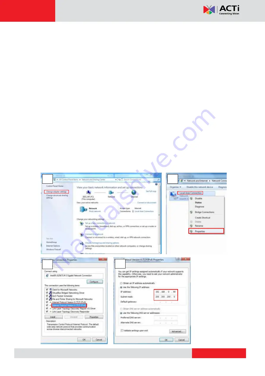
Manually adjust the IP address of the PC 

In the following example, based on Windows 7, we will configure the IP address to 

192.168.0.99

 and set Subnet Mask to 

255.255.255.0

 by using the steps below: 


Summary of Contents for B913

Page 1: ...Indoor PTZ Speed Dome Camera Hardware Manual B913 B923 B934 I92 I92 I912 Ver 2018 08 09...

Page 2: ...he Power Adapter 12 Preparing the DI DO Connector 14 Installation Procedures 17 Mounting Solutions 17 Other Mounting Accessories 19 Mounting on the Ceiling 20 Using the Bundled Surface Mount 20 Using...

Page 3: ...www acti com Hardware Manual 3 How to Replace the Dome Cover 38 How to Reset the Camera 39 Accessing Camera 40 Configure the IP Addresses 40 Access the Camera 44...

Page 4: ...or removing covers may expose you to dangerous voltage or other hazards Refer all servicing to qualified service personnel Trademarks ACTi and ACTi logos are registered trademarks of ACTi Corporation...

Page 5: ...urning the equipment off and on the user is encouraged to try to correct the interference by one or more of the following measures Reorient or relocate the receiving antenna Increase the separation be...

Page 6: ...rm etc in a dry place protected from weather Servicing Do not attempt to service this product yourself Refer all servicing to qualified service personnel Damage Requiring service Disconnect this produ...

Page 7: ...ity 30x optical B923 3MP Video Analytics Indoor Speed Dome Day Night Extreme WDR Superior Low Light Sensitivity 30x optical B934 2MP Video Analytics Indoor Speed Dome with D N Extreme WDR SLLS 30x Zoo...

Page 8: ...Contents Camera Power Adapter Universal Plug Converter Surface Mount Mounting Screw Kit Fixing Bracket Drill Template Terminal Block for Power Terminal Block for DIO DO Quick Installation Guide Warra...

Page 9: ...put device has a built in amplifier Connecting an ordinary microphone will dwarf sounds and will result in inaudible recording 3 DC 12V Power Input In case the camera is connected to a non PoE Power o...

Page 10: ...has a built in amplifier Connecting an ordinary microphone will dwarf sounds and will result in inaudible recording 3 DC 12V Power Input In case the camera is connected to a non PoE Power over Etherne...

Page 11: ...the dome cover it is recommended to retain the plastic covering the dome cover until the camera is completely installed However the plastic has been removed on the pictures in this documentation to s...

Page 12: ...oE switch or your PoE switch has limited power supply you can use the bundled power adapter and directly connect the camera to a power outlet The power adapter must be connected to the supplied termin...

Page 13: ...ires 3 Connect the wire with the white stripe to the 12V pin and the other to the GND pin 4 Tighten the screws of the 12V pin and the GND pins to secure the wire connection 5 Attach one of the bundled...

Page 14: ...example you can connect an alarm horn to the camera as such when an event occurs inside the camera e g detected intruder the alarm horn will sound Other common DO device applications are motion trigge...

Page 15: ...ased on these specifications if the DI device has a voltage of 0V 30V or the DO device has a voltage of 24V 50mA then the camera can supply internal power to these devices and there is no need to conn...

Page 16: ...pecifications and make sure they match the above design The triggering circuit voltage has to be around 12V DC and the switch controlled circuit voltage has to match the external power supply e g 110V...

Page 17: ...mera package See Using the Bundled Surface Mount on page 20 for mounting instructions Flush Mount Suitable when mounting the camera discretely above dropped ceilings wherein only the dome cover will b...

Page 18: ...ole Mount Suitable when mounting the camera on vertical poles PMAX 0110 PMAX 0303 PMAX 0503 Horizontal Pole Mount Suitable when mounting the camera on horizontal poles PMAX 0110 PMAX 0102 PMAX 0503 Co...

Page 19: ...nsion Tubes NOTE For more information about the mounting solutions and accessories please check the Mounting Accessory Selector in our website http www acti com mountingselector Except for the Surface...

Page 20: ...for mounting instructions Pendant Mount To install the camera on high ceilings and the camera will be lowered by the pendant mount See Using the Pendant Mount on page 29 for mounting instructions Usi...

Page 21: ...the holes on the camera using the supplied screw holes marked below The fixing bracket will fix the camera position when mounted later 5 Align and insert the camera base hooks to the mounting holes o...

Page 22: ...in etc to the camera NOTE The cables may be routed along the ceiling if the camera is installed on a hard ceiling Or the cables may pass through a hole on the ceiling if the camera is installed on a d...

Page 23: ...e camera package Contact your sales agents to purchase Before installation prepare the following Flush Mount Kit Other Tools not supplied Flush Mount Drill template Screw 1 Foam rubber pads 3 Fixing b...

Page 24: ...from the mount as marked below Then set the cover ring aside 2 Peel off the lining of the three 3 foam rubber pads and attach a rubber pad to each retaining bracket Step 3 Loosen the Retaining Bracke...

Page 25: ...dge is flat on the ceiling 2 Position the retaining brackets to hold the mount on the ceiling NOTE The following illustration shows how the flush mount will look like when viewed from inside the ceili...

Page 26: ...e the network cable power adapter and other cables if necessary are routed on the outer gap of the metal bracket 4 Attach the fixing bracket to one of the holes on the camera using the supplied screw...

Page 27: ...then insert the camera through the bracket NOTE Take note that the network cable must be bent to insert the camera into the mount If the network cable you are using is not flexible or too rough to be...

Page 28: ...omes aligned with the hole on the metal bracket 3 Tighten the screw on the fixing bracket to fix the camera position This is to avoid accidental camera movement as the camera performs PTZ functions St...

Page 29: ...onfiguration if the cable can directly enter the ceiling Mounting Screws included in the mount kit package Network Extension Cable included in the PMAX 0110 kit Screwdriver not included Step 1 Install...

Page 30: ...ong enough you may use one or more extension tubes purchased separately Step 2 Install the Mount Kit PMAX 0110 1 Insert the cables from the tube into the mount kit and route them to pass through the o...

Page 31: ...the camera If necessary connect the other cables such as power adapter DI DO etc to the corresponding connectors NOTE Try to push the network cable further into the mount T I P If the network cable t...

Page 32: ...the camera counter clockwise to secure the hooks to the mount 4 On the top of the mount kit attach three 3 screws included in the mount kit package to secure the camera to the mount The final installa...

Page 33: ...installation requirements Using the L Type Wall Mount To install the camera on a straight wall use the L Type Wall Mount The camera will be facing down as if installed on a ceiling NOTE The L Type Wal...

Page 34: ...the cable holes A to B as marked below With the cable s dangling attach three 3 screws included in the camera package to install the L type wall mount onto the wall Step 2 Install the Camera 1 Connec...

Page 35: ...35 2 Align and insert the camera base hooks to the mounting holes 3 Slide the camera clockwise to secure the hooks to the mount 4 Attach three 3 screws included in the L type wall mount package to se...

Page 36: ...Memory Card NOTE Supports microSDHC and microSDXC cards B913 B923 B934 1 Rotate the dome cover counter clockwise to remove it 2 Insert the memory card into the card slot near the camera shot 3 Push th...

Page 37: ...e card completely until it clicks into place How to Remove the Memory Card In case there is a need to remove the card make sure to access the camera Web Configurator to safely unmount the card first s...

Page 38: ...your surveillance needs you may want to replace the bundled dome cover with a smoke dome cover available for purchase To replace the dome cover do the following 1 Rotate the dome cover counter clockwi...

Page 39: ...nd therefore the camera cannot be accessed In case of IP address mask or allow deny filter related issues resulting with inability to modify these settings In case of connectivity issues or abnormal v...

Page 40: ...DHCP server running then you do not need to configure the IP addresses at all both the camera and the PC would request a unique IP address from the DHCP server automatically In such case the camera wi...

Page 41: ...t only discover the cameras but also list lots of valuable information such as IP and MAC addresses serial numbers firmware versions etc and allows quick configuration of multiple devices at the same...

Page 42: ...o the network and it does not detect any DHCP services it will automatically assign itself a default IP 192 168 0 100 Whereas the default port number would be 80 In order to access that camera the IP...

Page 43: ...IP Utility With the procedure shown above all the cameras will have unique IP addresses starting from 192 168 0 101 In case there are 20 cameras selected the last one of the cameras would have the IP...

Page 44: ...hen prompted so No other third party utilities are required to be installed in such case The examples in this manual are based on Internet Explorer browser in order to cover all functions of the camer...

Page 45: ...com Hardware Manual 45 Before logging in you need to know the factory default Account and Password of the camera Account Admin Password 123456 For further operations please refer to the Firmware User...

Page 46: ...Copyright 2018 ACTi Corporation All Rights Reserved 7F No 1 Alley 20 Lane 407 Sec 2 Ti Ding Blvd Neihu District Taipei Taiwan 114 R O C TEL 886 2 2656 2588 FAX 886 2 2656 2599 Email sales acti com...

Reviews: