background image

www.acti.com


Hardware Manual 


23 

4.


Connect the camera cable connector to the 

Camera

 port of the main unit. 


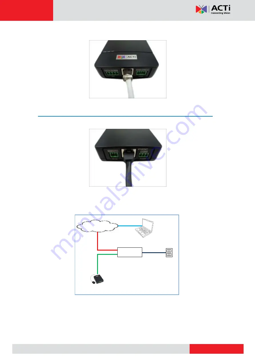
Step 4: Connect to the Network 

1.


Connect one end of a network cable to the 

Ethernet

 port of the main unit. 


2.


Connect the other end to a switch or injector. Then, connect the switch or injector to a 

network or PC and a power source. See Power-over-Ethernet (PoE) example connection 

diagram below. 


Network 

AC Power 

Source 

PoE Injector / 

PoE Switch 

Power Cable 

Ethernet Cable 

Ethernet Cable 
(Data + Power) 

Ethernet Cable 

(Data) 

Camera 


In case of using a non-PoE switch, power up the camera using a power adapter (not 

supplied). Se

Connecting a Power Adapter (Optional)

 on page 25 for more 

information.   

Summary of Contents for Q113

Page 1: ...L Shape Pinhole Covert Hardware Manual Q113 Q115 2016 06 16...

Page 2: ...the Surface Mount 13 Step 1 Mount the Camera 13 Step 2 Route and Connect the Camera Cable 14 Step 3 Connect to the Network 14 Step 4 Access the Camera Live View 15 Installing the Camera Using the Flu...

Page 3: ...ower Adapter Optional 25 Connecting DI DO Devices Optional 27 Connecting Audio In Out Devices Optional 30 Connecting Serial Devices Optional 31 Other Accessories 32 How to Install Remove the Memory Ca...

Page 4: ...g or removing covers may expose you to dangerous voltage or other hazards Refer all servicing to qualified service personnel Trademarks ACTi and ACTi logo are registered trademarks of ACTi Corporation...

Page 5: ...urning the equipment off and on the user is encouraged to try to correct the interference by one or more of the following measures Reorient or relocate the receiving antenna Increase the separation be...

Page 6: ...vice Disconnect this product from the power supply immediately and refer servicing to qualified service personnel under the following conditions 1 When the power supply cord or plug is damaged 2 If li...

Page 7: ...nual 7 Introduction The List of Models This hardware manual contains the following models Q113 2MP Indoor L Shape Pinhole Covert with Basic WDR SLLS Fixed lens Q115 5MP Indoor L Shape Pinhole Covert w...

Page 8: ...Terminal Block for Power Terminal Block for DI DO Terminal Block for Audio In Out Terminal Block for RS 232 Quick Installation Guide Warranty Card Mounting Accessories Surface Mount Flush Mount Tilte...

Page 9: ...Input Output Connects to digital input or output devices such as an alarm trigger panic button etc Digital Input DI and Digital Output DO devices are used in applications like motion detection event t...

Page 10: ...this connector to connect the camera to an external power adapter See Connecting a Power Adapter Optional on page 25 for information 9 Reset Button Restores the factory default settings of the camera...

Page 11: ...ng the Camera Using the Flush Mount on page 16 Tilted Wall Mount Suitable when mounting the camera on high walls The camera is tilted 20 to capture a larger viewing angle below the camera and less on...

Page 12: ...long The main unit can be installed apart from where the camera is mounted like in a secured area or separate room Mounting on DIN Rail 1 Attach the lower end of the main unit to the DIN rail 2 Sligh...

Page 13: ...e room Before installation determine the location to mount the camera and the main unit Consider that the camera cable is 12 meters long Step 1 Mount the Camera 1 Determine the location to install the...

Page 14: ...e main unit see Installing the Main Unit on page 12 for details 2 Route the camera cable towards the main unit accordingly Probably along the surface or may pass through a hole on the surface and towa...

Page 15: ...e Ethernet Cable Data Power Ethernet Cable Data Camera In case of using a non PoE switch power up the camera using a power adapter not supplied See Connecting a Power Adapter Optional on page 25 for m...

Page 16: ...Supported surface thickness 1 10 mm Supported lens hole diameter 6 23 mm Camera cable length 12 meters If there is another surface behind the back of the surface must have space in between of at leas...

Page 17: ...h mount to the surface according to the marked area 6 The adhesive on the flush mount is sufficient to hold the mount against most types of surfaces Nevertheless a screw is bundled with the camera pac...

Page 18: ...de the camera through the flush mount 2 Attach the set screw to one of the holes on top of the flush mount to fix the depth of the lens position Meanwhile the final installation on the other side of t...

Page 19: ...e main unit see Installing the Main Unit on page 12 for details 2 Route the camera cable towards the main unit accordingly Probably along the surface or may pass through a hole on the surface and towa...

Page 20: ...e Ethernet Cable Data Power Ethernet Cable Data Camera In case of using a non PoE switch power up the camera using a power adapter not supplied See Connecting a Power Adapter Optional on page 25 for m...

Page 21: ...e floor area The main unit can be installed apart from where the camera is mounted like in a secured area or separate room Before installation consider the following Camera cable length 12 meters Moun...

Page 22: ...s the camera and the main unit to be installed apart such as in a separate area or room etc 1 The main unit should be mounted at this point if not install the main unit see Installing the Main Unit on...

Page 23: ...itch or injector Then connect the switch or injector to a network or PC and a power source See Power over Ethernet PoE example connection diagram below Network AC Power Source PoE Injector PoE Switch...

Page 24: ...and power up other devices such as digital input output audio or serial device See Cable Connections on page 25 for more information on connecting other devices Step 5 Access the Camera Live View See...

Page 25: ...er Optional The camera can be powered by a Power over Ethernet PoE switch that is IEEE802 3af compliant In case of using a non PoE switch or your PoE switch has limited power supply you can purchase a...

Page 26: ...nd the other to the GND pin 4 Tighten the screws of the 12V pin and the GND pins to secure the wire connection 5 Set the prepared power adapter for connection later Below is an example of a power adap...

Page 27: ...activated by the camera upon an event inside the camera For example you can connect an alarm horn to the camera as such when an event occurs inside the camera e g detected intruder the alarm horn wil...

Page 28: ...ransistor Open Collector Voltage Current 24V DC 50mA Typical Connection Based on these specifications if the DI device has a voltage of 0V 30V or the DO device has a voltage of 24V 50mA then the camer...

Page 29: ...pecifications and make sure they match the above design The triggering circuit voltage has to be around 12V DC and the switch controlled circuit voltage has to match the external power supply e g 110V...

Page 30: ...one of the pin combinations below Device Pin Mapping Instructions Audio Output GND Connect the wires of the audio output device to GND and AUDIO OUT AUDIO OUT Audio Input GND Connect the wires of the...

Page 31: ...se you need to connect the serial device to the supplied RS 232 terminal block To connect a serial device map the pins as below Terminal Block Wire Mapping Pin Number Label Main Unit Serial Device TX...

Page 32: ...nd microSDXC cards How to Insert the Memory Card 1 Open the memory card slot cover 2 Insert the memory card with the metal contacts facing down the main unit 3 Push the card until it clicks into place...

Page 33: ...rd In case there is a need to remove the card make sure to access the camera Web Configurator to safely unmount the card first see the camera Firmware User s Manual for more information Once unmounted...

Page 34: ...12 Connector with shielding is recommended RJ 12 Crimping Tool Scissors 2 Unsnap the ferrite core from the camera cable and set it aside for later use 3 Measuring from the camera end cut the cable ac...

Page 35: ...p 1 Brown 2 Stripe Brown 3 Unused 4 Unused 5 Stripe Blue 6 Blue 7 Push the wires into the connector all the way to the end 8 Place the connector into the crimping tool and cinch down to secure the RJ...

Page 36: ...with a distance of 30 mm from the cable connector NOTE The ferrite core is used to suppress electromagnetic interference EMI from the camera that may affect other devices as well as prevent the EMI fr...

Page 37: ...d the PC would request a unique IP address from the DHCP server automatically In such case the camera will immediately be ready for the access from the PC The user however might not know the IP addres...

Page 38: ...ial numbers firmware versions etc and allows quick configuration of multiple devices at the same time Search and downloand IP Utility for free from http www acti com DownloadCenter When you launch IP...

Page 39: ...o the network and it does not detect any DHCP services it will automatically assign itself a default IP 192 168 0 100 Whereas the default port number would be 80 In order to access that camera the IP...

Page 40: ...IP Utility With the procedure shown above all the cameras will have unique IP addresses starting from 192 168 0 101 In case there are 20 cameras selected the last one of the cameras would have the IP...

Page 41: ...t Explorer browsers free third party software plug ins must be installed to the PC first to be able to get the live video feed from the camera Browser Required Plug In Safari QuickTime http www apple...

Page 42: ...ddress bar http 192 168 0 100 Upon successful connection to the camera the user interface called Web Configurator would appear together with the login page The HTTP port number was not added behind th...

Page 43: ...Copyright 2015 ACTi Corporation All Rights Reserved 7F No 1 Alley 20 Lane 407 Sec 2 Ti Ding Blvd Neihu District Taipei Taiwan 114 R O C TEL 886 2 2656 2588 FAX 886 2 2656 2599 Email sales acti com...

Reviews: