background image

www.acti.com


TCM-1231 Series Hardware User’s Manual 


16 

Basic Connections 


Follow the procedures below to connect the IP device to the respective apparatuses.     


If you have a PoE (Power over Ethernet) supported switch or injector:   

1)  Connect your IP Camera to the Switch / Injector by CAT5 or CAT6 cables with RJ45 

connector. 

2)  Connect your Switch / Injector to PC with another CAT5 / CAT6 network cable. 


If your switch does not support PoE, and you are powering the camera with power 

adaptor:   

1)  Connect the power adaptor to IP Camera   

2)  Connect IP device’s Ethernet port to Network switch (via RJ45 connectors).   

3)  Connect a PC to the Ethernet switch (via RJ45 connectors) 


Please refer our 

PoE Guide

 for more details on Power over Ethernet related concepts.   

VoIPon   www.voipon.co.uk   sales@voipon.co.uk   Tel: +44 (0)1245 808195   Fax: +44 (0)1245 808299

Summary of Contents for TCM-1231 Series

Page 1: ...TCM 1231 Series H 264 Megapixel Outdoor IP IR D N PoE Bullet Camera Hardware User s Manual Ver 2012 8 29 VoIPon www voipon co uk sales voipon co uk Tel 44 0 1245 808195 Fax 44 0 1245 808299 ...

Page 2: ...on 12 Remove the back cover by unscrewing the three attachments 12 Remove the sunshade by unscrewing the two screws 12 How to Do the Waterproof Installation 13 Basic Connections 16 Product Specification 17 2 Accessing Camera 18 If you have DHCP server router in your network 18 If you do NOT have DHCP server router in your network 18 VoIPon www voipon co uk sales voipon co uk Tel 44 0 1245 808195 F...

Page 3: ...nform your local office if you find any inaccuracies or omissions We cannot be held responsible for any typographical or technical errors and reserve the right to make changes to the product and manuals without prior notice FCC CE Regulation NOTE This equipment has been tested and found to comply with the limits for a Class A digital device pursuant to Part 15 of the FCC Rules These limits are des...

Page 4: ...re User s Manual 4 1 Introduction Package Contents TCM 1231 Series No Bracket Included Product CD Terminal Blocks for Power Audio and DIO Warranty Card VoIPon www voipon co uk sales voipon co uk Tel 44 0 1245 808195 Fax 44 0 1245 808299 ...

Page 5: ... sensors are required You may assign up to 3 video motion detection areas By tuning the object size and sensitivity it will reliably detect objects passing though in view Hardware motion detection also offers better sensitivity and faster response time than software motion detection Powerful Bundled Surveillance Software To extend the capabilities of the camera a powerful surveillance program is i...

Page 6: ...ed function records video time in the video stream Therefore each image frame is marked with its original recording time It is very useful when users want to find the video at an exact time or between a certain time intervals VoIPon www voipon co uk sales voipon co uk Tel 44 0 1245 808195 Fax 44 0 1245 808299 ...

Page 7: ...nstall this device and the power supply in a dry place protected from weather Servicing Do not attempt to service this video product yourself as opening or removing covers may expose you to dangerous voltage or other hazards Refer all servicing to qualified service personnel Damage Requiring service Disconnect this video product from the power supply immediately and refer servicing to qualified se...

Page 8: ...eo product to its normal operation Safety Check Upon completion of any service or repairs to this video product ask the service technician to perform safety checks to determine if the video product is in proper operating condition VoIPon www voipon co uk sales voipon co uk Tel 44 0 1245 808195 Fax 44 0 1245 808299 ...

Page 9: ... Terminal Connector This IP Camera supports DI O Audio input output via terminal block Used in applications like motion detection event triggering time lapse recording alarm notifications etc the I O terminal connector provides an interface to respective devices The Terminal Block wiring diagram is as follows PIN NAME DESCRIPTION 1 12V DC Power Input 2 GND Ground Pin VoIPon www voipon co uk sales ...

Page 10: ...ription Spec DO Transistor Output Uses an open collector NPN transistor with the emitter connected to the GND pin If used with an external relay a diode must be connected in parallel with the load for protection against transient voltages Max load 100mA Max voltage 24V DC to the transistor DI Digital Input Connect to GND to activate or leave floating or unconnected to deactivate Must not be expose...

Page 11: ... then release the reset button This length of time fluctuates slightly with the environment The Power LED light will come back on and stay on after a few more seconds The unit will start up with factory default settings automatically On 3s On 1s Power On About 20 Seconds Stay On Off about 15s Off 10 15s Restore to Default Complete 4 Ethernet Port The IP device connects to the Ethernet via a standa...

Page 12: ...e User s Manual 12 Preparing for Installation Remove the back cover by unscrewing the three attachments Remove the sunshade by unscrewing the two screws VoIPon www voipon co uk sales voipon co uk Tel 44 0 1245 808195 Fax 44 0 1245 808299 ...

Page 13: ...matches with the conduit gland is 1 2 Please note that the conduit gland is included to the package of the bullet camera The following images show the step by step procedure of completing the water proof installation 1 Disassemble the conduit gland as shown on the photo 2 Pull the network cable through the flex conduit Please note that the size of the conduit and the gland is big enough to let the...

Page 14: ...a 5 The fourth piece locking nut is used to lock the gland firmly from the inside of the back side cover 6 Pull the network cable through the back side cover of the camera 7 Connect the flex conduit to the back side cover of the camera VoIPon www voipon co uk sales voipon co uk Tel 44 0 1245 808195 Fax 44 0 1245 808299 ...

Page 15: ...and need an additional power cord then please connect it at this stage too 10 Tighten the screws of the back side of the camera properly 11 Finally the bullet camera with properly mounted flex conduit as well as with proper outdoor bracket would look like this The camera is now ready to withstand even the most severe rain storms VoIPon www voipon co uk sales voipon co uk Tel 44 0 1245 808195 Fax 4...

Page 16: ...nector 2 Connect your Switch Injector to PC with another CAT5 CAT6 network cable If your switch does not support PoE and you are powering the camera with power adaptor 1 Connect the power adaptor to IP Camera 2 Connect IP device s Ethernet port to Network switch via RJ45 connectors 3 Connect a PC to the Ethernet switch via RJ45 connectors Please refer our PoE Guide for more details on Power over E...

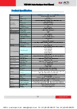
Page 17: ... p 1Vrms terminal block 1 TTL Terminal Block 1 TTL Terminal Block Factory Default System Status 28K 6M bps 18 fps at SXGA 26 fps at HD720 30 fps at VGA QVGA and QQVGA 8kHz Mono PCM Unbalanced 1 4Vp p 1Vrms terminal block 8kHz Mono PCM Auto Indoor1 Indoor2 Outdoor1 Outdoor2 Hold Current Manual CE FCC IP66 Weatherproof casing with IP66 standard Ethernet 10 100 Base T RJ 45 connector TCP UDP HTTP HTT...

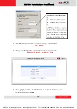
Page 18: ... you do NOT have DHCP server router in your network 1 Configure your PC to use the same subnet by changing your PC s IP address to the subnet with prefix 192 168 0 XXX The last number should be anything from 1 to 254 except 100 and other occupied IP addresses Subnet mask should be 255 555 255 0 2 The default IP used by this device is 192 168 0 100 Please make sure your PC is NOT using this address...

Page 19: ...ter logging in you will see the video from camera To go to the main menu click the Setup button on the top left Please set the settings as below IP address 192 168 0 xxx Subnet mask 255 255 255 0 NOTE xxx should be a number from 1 to 254 except 100 which is used by the IP device Please also make sure that no two equipments use the same IP address in the same network VoIPon www voipon co uk sales v...

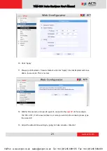
Page 20: ...t device is connected to the network no two devices use the same IP Please perform the following steps 7 Go to Network Connection Type 8 Change the IP mode to Static 9 Change the IP to 192 168 0 101 or any other unused IPs Do NOT use the PC s IP address or 192 168 0 100 If this is not the first device you add to the network please also avoid other devices IPs VoIPon www voipon co uk sales voipon c...

Page 21: ...a few seconds This is normal 12 Wait for 30 seconds and open IE again to connect to the new IP In this example 192 168 0 101 For the second device or more you add into the network please type the correct IP 13 Adjust the default Video setting by going to Video Audio Media 1 VoIPon www voipon co uk sales voipon co uk Tel 44 0 1245 808195 Fax 44 0 1245 808299 ...

Page 22: ...www acti com TCM 1231 Series Hardware User s Manual 22 VoIPon www voipon co uk sales voipon co uk Tel 44 0 1245 808195 Fax 44 0 1245 808299 ...

Reviews: