background image

www.acti.com

Hardware Manual 


10 


Physical Description 

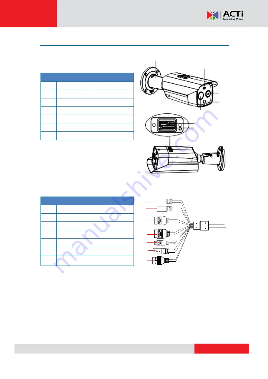
Camera Body 


Item 

Bracket 

Speaker 

Optical Lens 

Thermal Lens 

White Light Lamp 

Reset Button 

Memory Card Slot 


Cable Description 


Item 


Audio Output 

Audio Input 

10 

Digital Input / Output 1 (Alarm1) 

11 

Digital Input / Output 2 (Alarm2) 

12 

RS-485 

13 

Power (DC 12V) 

14 

Ethernet Port 


NOTE: 


Digital input cables are labeled as ALARM-IN1 and ALARM-IN2.   

Digital output cables are labeled as 1A,1B and 2A, 2B. 


To reset the camera to default parameters, hold the Reset Button and power on the 

camera. After powering on the camera, continue holding the Reset Button for about 

10 seconds.   


4


10 

11 

12 

13 

14 

Summary of Contents for VMGB-352

Page 1: ...Metadata Camera Hardware Manual VMGB 352 Ver 2022 08 05...

Page 2: ...tion 10 Installation Procedures 11 Before Installation 11 Install the Memory Card 12 Determine Wide Range Coverage 13 Install the Camera 14 Manage the Cables 15 Using the Cable Gland 15 Using a Power...

Page 3: ...ocal office if you find any inaccuracies or omissions We cannot be held responsible for any typographical or technical errors and reserve the right to make changes to the product and manuals without p...

Page 4: ...hall not assume any responsibility for problems caused by unauthorized repair or maintenance Maintenance If there is dust on the front glass surface remove the dust gently using an oil free brush or a...

Page 5: ...instruction manual may cause harmful interference to radio communications Operation of this equipment in a residential area is likely to cause harmful interference in which case the user will be requ...

Page 6: ...roduct documentation for specific battery information The battery is marked with this symbol which may include lettering to indicate cadmium Cd lead Pb or mercury Hg For proper recycling return the ba...

Page 7: ...packaging while transporting it Keep all wrappers after unpacking them for future use In case of any failure occurred you need to return the device to the factory with the original wrapper Transporta...

Page 8: ...configure all the passwords and other security settings about the device and keep your user name and password Maintenance Clean the lens with soft and dry cloth or wiping paper to avoid scratching it...

Page 9: ...Guide Warranty Card Screw Pack IMPORTANT When the camera is taken out from the box the lens cover is covered by a thin film DO NOT remove this film It is used to protect the lens cover from scratches...

Page 10: ...igital Input Output 1 Alarm1 11 Digital Input Output 2 Alarm2 12 RS 485 13 Power DC 12V 14 Ethernet Port NOTE Digital input cables are labeled as ALARM IN1 and ALARM IN2 Digital output cables are labe...

Page 11: ...wered off during the installation Check the specification of the products for the installation environment Make sure that the wall is strong enough to withstand four times the weight of the camera and...

Page 12: ...ry card for local recording unscrew and remove the memory card slot cover NOTE Do not hot plug the memory card after it has been inserted and the power turned on otherwise the camera or the card might...

Page 13: ...23 m 46 m 51 m 74 m 110 m 184 m 257 m Identification range Vehicles 35 m 70 m 79 m 113 m 169 m 282 m 395 m Identification range Humans 11 m 23 m 26 m 37 m 55 m 92 m 129 m Take human as 0 5 m width 1...

Page 14: ...ent walls drill four 5 installation holes according to the template recommended depth 25 mm and insert the expansion screws Otherwise skip the step 3 Drill a cable hole in the center 4 Install the cam...

Page 15: ...ction and use a waterproof tape to protect other cable connections See Using a Power Adapter Optional on page 18 for more information DISCLAIMER ACTi will not be responsible for camera damage caused b...

Page 16: ...Hardware Manual 16 3 Insert the clamping nut into the Ethernet cable 4 Insert the sealing insert through the Ethernet cable 5 Insert the cable through the gland body 6 Push the sealing insert into th...

Page 17: ...the camera connector 8 Attach the gland body to the camera connector 9 Attach the clamping nut to the gland body to complete the cable solution NOTE Make sure the clamping nut is tightly attached to...

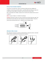
Page 18: ...nnection with waterproof tape to ensure it is protected NOTE The power adapter is not bundled in the package CAUTION The cable connector must not be exposed and must be kept away from water If the cab...

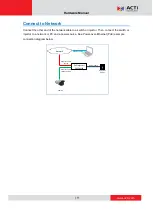
Page 19: ...ble to a switch or injector Then connect the switch or injector to a network or PC and a power source See Power over Ethernet PoE example connection diagram below Network AC Power Source PoE Injector...

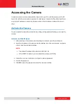
Page 20: ...the camera first by setting a strong password before you can use the camera Activate via Web Browser 1 After powering on the camera and connecting to a network open the web browser 2 Input the IP add...

Page 21: ...rial numbers firmware versions etc and allows quick configuration of multiple devices at the same time The IP Utility can be downloaded for free from http www acti com IP_Utility 1 Open IP Utility 2 C...

Page 22: ...Copyright 2022 ACTi Corporation All Rights Reserved 7F No 1 Alley 20 Lane 407 Sec 2 Ti Ding Blvd Neihu District Taipei Taiwan 114 R O C TEL 886 2 2656 2588 FAX 886 2 2656 2599 Email sales acti com...

Reviews: