background image

CBE25 

Manuale tecnico – Technical manual


Code  
MT-CBE25-02021080-R00 

Page 11/16 


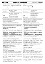
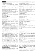
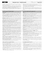
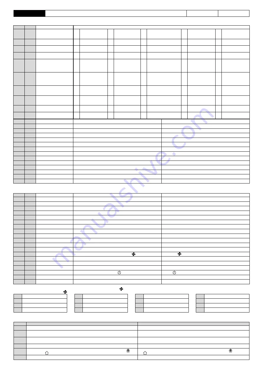
Tabella 1: Parametri di configurazione principali


Table 1: Main configuration parameters


DFLT 

PAR. 

Descrizione - Description 

Valori impostabili - Set values 

P01 

Tipo di impianto 
System type 

Sistema a 2-tubi 
2-pipes system 

Sistema a 4 tubi 
4-pipe system 

Resistenza 
Electric heater


Resistenza integrante 
Integrating Electric 
heater 

Pompa di calore 
Heat pump


P02 

Selezione estate/inverno 
Heating/cooling selection 

Manuale 
Manual 

Automatica 
Automatic 

Centralizzata 
Remote


P03 

Regolazione caldo 
Heating regulation 

Ventilatore sempre ON 

Always ON fan


Valvola sempre ON 

Always ON valve


Regola valvola  e ventilatore 
Regulates valve and fan 

Ventilatore sempre OFF 
Always OFF fan 

Valvola sempre OFF 
Always OFF valve 

P04 

Regolazione freddo 
Cooling regulation 

Ventilatore sempre ON 

Always ON fan


Valvola sempre ON 

Always ON valve


Regola valvola  e ventilatore 
Regulates valve and fan 

Ventilatore sempre OFF 
Always OFF fan 

Valvola sempre OFF 
Always OFF valve 

P05 

Tipo uscita caldo 
Heating output type 

Servocomando a 3 
punti flottante 
Floating 3-point 
actuator 

Valvola ON/OFF NC 
NC ON/OFF valve 

Valvola ON/OFF NA 
NO ON/OFF valve 

Valvola ON/OFF NC 
proporzionale (PWM) 
Proportional ON/OFF 
NC Valve (PWM) 

Valvola ON/OFF NA 
proporzionale (PWM) 
Proportional ON/OFF 
NO Valve (PWM)


P06 

Tipo uscita freddo 
Cooling output type 

Servocomando a 
3-punti flottante 
Floating 3-point 
actuator 

Valvola ON/OFF NC 
NC ON/OFF valve 

Valvola ON/OFF NA 
NO ON/OFF valve 

Valvola ON/OFF NC 
proporzionale (PWM) 
Proportional ON/OFF 
NC Valve (PWM) 

Valvola ON/OFF NA 
proporzionale (PWM) 
Proportional ON/OFF 
NO Valve (PWM)


P07 

Ingresso sensore mandata 
acqua 
Water supply sensor input 

Non visualizza temp. 
Do not show temperat. 

Visualizza temperat. 
Show temperature 

Contatto bimetallico (TM) 
Bimetallic contact (TM) 


P08 

Antistratificazione 
De-stratification 

Mai 
Never 

In 
raffreddamento 
Cooling only 

In riscaldamento 
Heating only 

Sempre 
Always 


P09 

Stato On/Off powerup 
On/Off state at power up 

Precedente 
Last 

Predefinito On 
Always ON 

Predefinito off 
Always OFF 


P10 

Sonda temp. aria ambiente 
Room temperature sensor 

Esterna 
External 


0.0 

P11 

-10.0 ... +10.0 

Correzione temperatura ambiente (°C) 

Room temperature correction (offset) (°C) 

10.0 

P12 

5.0 ... 35.0 

Temperatura Set-point limite inferiore inverno (°C) 

Heating Set-point temperature knob lower limit (°C) 

30.0 

P13 

5.0 ... 35.0 

Temperatura Set-point limite superiore inverno (°C) 

Heating Set-point temperature knob upper limit (°C) 

10.0 

P14 

5.0 ... 35.0 

Temperatura Set-point limite inferiore estate (°C) 

Cooling Set-point temperature knob lower limit (°C) 

30.0 

P15 

5.0 ... 35.0 

Temperatura Set-point limite superiore estate (°C) 

Cooling Set-point temperature knob upper limit (°C) 

0.0 

P16 

0.0 ... 15.0 

Soglia temperatura antigelo (°C) 

Anti-freeze threshold temperature (°C) 

2.0 

P17 

0.0 ... 10.0 

Riduzione economy (°C) 

Economy reduction (°C) 

0.2 

P18 

0.2 ... 1.0 

Isteresi temperatura ambiente (°C) 

Room temperature hysteresis (°C) 

3.0 

P19 

0.0 ... 11.0 

Ampiezza zona neutra (°C) 

Neutral zone width (°C) 

P20 

0 ... 600 

Ritardo accensione ventilatore (secondi) 

Fan delay at turn-on (seconds) 

P21 

0 ... 600 

Ritardo spegnimento ventilatore (secondi) 

Fan delay at turn-off (seconds) 

40 

P22 

0 ... 99 

Soglia temperatura acqua di mandata inverno (°C) 

Heating delivery temperature threshold (°C)


99 

P23 

0 ... 99 

Soglia temperatura acqua di mandata estate (°C) 

Cooling delivery temperature threshold (°C)


P24 

0 ... 50 

Tempo avviso filtro sporco (x 100 ore) 

Dirty filter warning time (x 100 hours) 


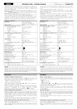
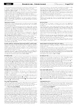
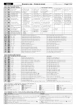
Tabella 2: Parametri di configurazione estesi


Table 2: Extended configuration parameters 

DFLT 

PAR. 

Valori impostabili - Set Values  Descrizione 

Description 

17 

C01 

0…24 

Soglia inferiore changeover (°C) 

Changeover lower threshold (°C) 

30 

C02 

26…48 

Soglia superiore changeover (°C) 

Changeover upper threshold (°C) 

150 

C03 

30...500 

Tempo apertura servocomando caldo (secondi) 

Heating floating actuator opening time (seconds) 

150 

C04 

30...500 

Tempo apertura servocomando freddo (secondi) 

Cooling floating actuator opening time (seconds) 

2.0 

C05 

0.8...8.0 

Banda proporzionale caldo (°C) 

Heating proportional band (°C) 

2.0 

C06 

0.8...8.0 

Banda proporzionale freddo (°C) 

Cooling proportional band (°C) 

C07 

0...60 

Tempo integrativo caldo (minuti) 

Heating integrating time (minutes) 

C08 

0...60 

Tempo integrativo freddo (minuti) 

Cooling integrating time (minutes) 

C09 

0...15 

Temporizzazione freddo (minuti) 

Cooling output timing (min) 

20 

C10 

0…50 

Potenza minima valvola caldo (%) 

Heating valve minimum power (%) 

C11 

0…50 

Potenza minima valvola freddo (%) 

Cooling valve minimum power (%) 

C12 

1…3 

Numero velocità del motore ventilatore 

Fan motor speeds number 

C13 

0…11 (Tab.3) 

Velocità ventilatore impostabili dal pulsante 

Fan speed        button limitation 

C14 

0…22 (Tab.4) 

Funzione associata all’ingresso 

piazzola M13/EI


Pitch 

M13/EI 

input function 

C15 

0…22 (Tab.4) 

Funzione associata all’ingresso 

piazzola M14/RDC-ECO


Pitch 

M14/RDC-ECO

 input function 

C16 

0…22 (Tab.4) 

Funzione associata all’ingresso  

piazzole M15/CF + M16/COM-CF


Pitches


M15/CF + M16/COM-CF

 input function 

C17 

0…7 (Tab.5) 

Modalità impostabili da pulsante 

On/Off      button limitation 

1.5 

C18 

0.0…20.0 

∆ setpoint integrazione (°C) 

∆ integration set point (°C) 

C19 

0 - 1 

Visualizzazione di default (

0

 Temp. ambiente, 

1

 Temp. Set.Point) 

Default display (

0

 Room temperature, 

1

 Set Pont temperature) 


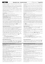
Tabella 3: Parametro C13 - Selezione velocità ventilatore impostabili da pulsante 


Table 3: C13 parameter - Fan speed           button limitation.


 2 

 3 

 AUTO


OFF 

 1 

 2 

 AUTO


12 

 2 

 3


 2 

 AUTO


OFF 

 1 

 AUTO


13 

 2


 AUTO


OFF 

 1


10 


14 

OFF 

 1 

 2 

 3


OFF 

 1 

 2 

 3 

 AUTO


OFF


11 

AUTO 


15 

OFF 

 1 

 2


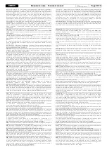
Tabella 4: PARAMETRI C14, C15, C16 - Funzione associabile agli ingressi M13/EI, M14/RDC-ECO e M15-M16/CF. 
Table 4: PARAMETERS C14, C15, C16 - Functions associated to M13/EI, M14/RDC-ECO and M15-M16/CF inputs 

Value 

Descrizione 

Description 

Nessuna funzione associata.


No function associated.


Funzione “Estate/Inverno centralizzata” (contatto chiuso= estate); il parametro 

P02 

deve essere configurato su 2.


“Centralised Summer/Winter” function (closed contact = summer); 

P02 

parameter 

configured to 2.


Funzione “Estate/Inverno centralizzata invertita” (contatto chiuso=inverno); il 
parametro 

P02 

deve essere configurato su 2.


“Reversed centralised Summer/Winter” function (closed contact = winter); 

P02 

parameter configured to 2.


Funzione “Economy” (contatto chiuso=riduzione).


“Economy” function (closed contact = reduction).


Funzione “Economy” (contatto chiuso=riduzione) - il display visualizza l’icona 
(presenza) o         (assenza).


“Economy” function (closed contact = reduction) - display shows the        (present) 
or        (absent) icon.


Funzione “Economy invertita” (contatto aperto=riduzione).


“Reversed economy” function (contact open = reduction).


Summary of Contents for CBE25

Page 1: ...Regolatore a bordo Alto Livello Multifunzione Controller on board High Level Multi Function MT CBE25 22026010 R00 ...

Page 2: ...i rimanda per le AVVERTENZE GENERALI Hereby manual is an integral part of the unit s manual on which the accessory is installed Please refer to hereby manual for GENERAL RECOMMENDATIONS L installazione deve essere effettuata da personale qualificato The installation must be performed by qualified personnel INSTALLAZIONE INSTALLATION 1 Installare il quadro comando 2 viti A B 1 Install the control p...

Page 3: ... per rendere il regolatore idoneo per alimentazione 24Vac Compatibilità SND A4 sonda aria remota inclusa TM 32 TM 42 termostati di minima accessorio addizionale SND W4 sonda acqua in alternativa a TM accessorio addizionale Se installata la sonda acqua SND W4 si rendono disponibili le seguenti funzioni Termostato minima temp acqua calda T impostabile Termostato max temp acqua fredda T impostabile C...

Page 4: ...display readout mode when depressed once it makes the display show the set point temperature In case the controller is configured to show the delivery water temperature this value will be displayed with a further button depression When changing the readout the controller informs the user about the temperature shown according to the following table Set point temperature Delivery water temperature R...

Page 5: ...pliance with the current safety standards and with a contact separation of at least 3 mm in all poles Installation and electrical wirings of this appliance must be made by qualified technicians and in compliance with the current standards Before wiring the appliance be sure to turn the mains power off COLLEGAMENTI ELETTRICI Il dispositivo può essere alimentato a 230V 50 60Hz oppure a 24V 50 60Hz S...

Page 6: ...e Materiale Colore ABS PC V0 autoestinguente Bianco segnale simile RAL9003 Case Material Color ABS PC V0 self extinguishing Signal white RAL 9003 Classificazione Secondo Regolamento 2013 811 CE Classe Contributo all efficienza energetica V 3 Classification under reg 2013 811 EC Class Contribution to energy efficiency V 3 GARANZIA WARRANTY Nell ottica di un continuo sviluppo dei propri prodotti il ...

Page 7: ...y the SND A4 external sensor wired to the RS SA connector The parameter P10 in the installer configuration is always set at 1 to select an external sensor and it cannot be modified The supply water temperature in the fan coil is acquired through a remote sensor SND W4 and can be displayed with 1 C resolution in the 0 C 99 C range The delivery water sensor does not have to be installed in case the ...

Page 8: ...e una riduzione dei consumi riducendo la temperatura di setpoint impostata di uno step configurabile quando in riscaldamento o aumentando il setpoint dello step configurabile quando in raffrescamento Lo step di riduzione si imposta con il parametro P17 se questo viene impostato a 0 0 la funzione Economy è disabilitata La modalità di risparmio Economy si attiva da pulsante come spiegato nel paragra...

Page 9: ...modo tentando di accedere alla configurazione comparirà sul display l icona lampeggiante La configurazione installatore è composta da due liste di parametri parametri principali da P01 a P24 tabella 1 parametri estesi da C01 a C19 tabella 2 I parametri estesi C01 C19 permettono una configurazione avanzata del termostato Per accedere ai parametri estesi quando il display visualizza COn all entrata ...

Page 10: ...In case of a black out the thermostat remembers its latest state and when the power returns it restarts with the same settings on off heating cooling etc Anyway in some situations it is requested that the thermostat restarts to a known state i e always OFF or always ON This can be accomplished by setting parameter P09 to 2 always restart from ON or 3 always restart from OFF P10 Selezione della son...

Page 11: ...ddo La potenza minima è quella percentuale di apertura della valvola proporzionale al di sotto della quale il ventilatore rimane spento per evitare che il ventilatore venga acceso quando la valvola non ha ancora cominciato ad aprire il flusso dell acqua C10 and C11 respectively represent the minimum power percentage of the heating and cooling proportioning valve The minimum power is the opening pe...

Page 12: ... delay at turn off seconds 40 P22 0 99 Soglia temperatura acqua di mandata inverno C Heating delivery temperature threshold C 99 P23 0 99 Soglia temperatura acqua di mandata estate C Cooling delivery temperature threshold C 0 P24 0 50 Tempo avviso filtro sporco x 100 ore Dirty filter warning time x 100 hours Tabella 2 Parametri di configurazione estesi Table 2 Extended configuration parameters DFL...

Page 13: ...ly if requested ordered SND W4 Sonda temperatura acqua in alternativa al termostato TM Water temperature sensor alternative to TM thermostat TM Termostato di minima temperatura acqua calda TM 32 TM 42 Minimum hot water temperature thermostat TM 32 TM 42 YV1 230V Valvola batteria principale 230V on off 2Tubi freddo caldo 4Tubi freddo Main coil valve 230V on off 2Pipe cooling heating 4Pipe cooling Y...

Page 14: ...ndard o speciale Standard in assenza di una richiesta specifica del cliente sulla modalità di funzionamento l unità viene cablata con questo schema elettrico Speciale Schema elettrico realizzato solo su specifica richiesta del cliente per ottenere una modalità di funzionamento differente da quella prevista dallo schema standard In questo caso il numero dello schema sarà riportato in conferma d ord...

Page 15: ...Tutto spento Tutto chiuso Off All off All closed On Modalità di funzionamento programmabile dall utente On Working mode totally programmable by the user Aria Air Acqua Water Alimentazione elettrica Power supply 230Vac 1Ph 50Hz AUTR Com Max Med Min C MV 6 min 5 4 3 2 1 max N Com BU RD WH BN M M BN BU X1 Dispositivi e montaggio a cura dell installatore Equipments to be installed by the installer 2 1...

Page 16: ...stallatore Equipments to be installed by the installer 2 1 BU BN GNYE PE BN BU 230V 50Hz N L PE PE IG 2P N L TM BN BU R 2no R Max WH RD Min BK RD TS TS M RES WH RD BK 1 STAGE NTC 10kΩ NTC 10kΩ YV1 230V Aria Air SND A4 Acqua Water SND W4 Alimentazione elettrica Power supply 230Vac 1Ph 50Hz AUTR Com Max Med Min C MV 6 min 5 4 3 2 1 max N Com BU RD WH BN M M BN BU X1 Dispositivi e montaggio a cura de...

Page 17: ...On Modalità di funzionamento programmabile dall utente On Working mode totally programmable by the user chiude closes apre open YV2 F230 comune common YV1 F230 Aria Air Alimentazione elettrica Power supply 230Vac 1Ph 50Hz AUTR Com Max Med Min C MV 6 min 5 4 3 2 1 max N Com BU RD WH BN M M BN BU X1 Dispositivi e montaggio a cura dell installatore Equipments to be installed by the installer 2 1 BU B...

Page 18: ......

Reviews: