CBE25
Manuale tecnico – Technical manual
Code
MT-CBE25-02021080-R00
Page 04/16
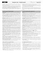
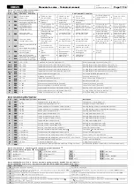
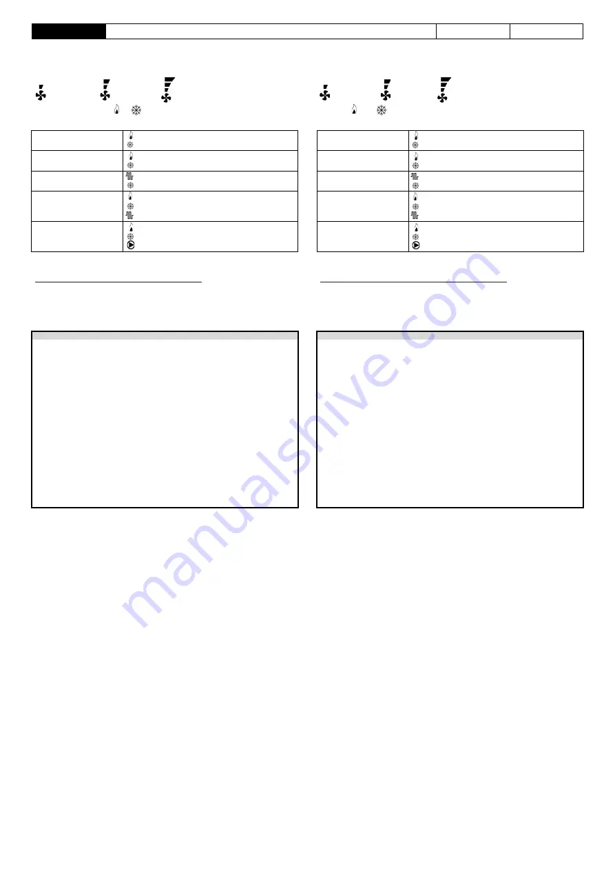
Sul display sono presenti anche dei simboli che identificano lo stato delle uscite: il
ventilatore e le valvole o altro carico collegato. I simboli “velocità ventilatore“
identificano lo stato del ventilatore: quando sono tutti spenti indicano ventilatore spento,
mentre quando sono accesi indicano ventilatore acceso secondo le seguenti indicazioni:
Velocità 1 Velocità 2 Velocità 3
Some symbols on the display show the outputs status: fan, valves or other connected
loads.
The “fan speed“ symbols show fan status: all off when fan is off; all lit when fan is on,
according to the following indications:
Speed 1 Speed 2 Speed 3
L’accensione dei simboli e identifica uno stato delle uscite valvola diverso a
seconda del tipo di impianto.
Symbols and indicates the status of the valve outputs which is different
depending on the type of system.
Sistema a due tubi
riscaldamento, valvola aperta
raffrescamento, valvola aperta
Two pipes system
heating mode, valve open
cooling mode, valve open
Sistema a quattro tubi
valvola caldo aperta
valvola freddo aperta
Four pipes system
heating valve open
cooling valve open
Sistema con resistenza
riscaldamento, resistenza accesa
raffrescamento, valvola freddo aperta
Electric heater system
heating mode, electric heater on
cooling mode, cooling valve open
Sistema con resistenza di
integrazione
riscaldamento, valvola aperta
raffrescamento, valvola aperta
riscaldamento, resistenza accesa
Integrating electric heater
system
heating mode, valve open
cooling mode, valve open
heating mode, electric heater on
Sistema pompa di calore
valvola di inversione riscaldamento
valvola di inversione raffreddamento
compressore acceso
Heat pump system
reversing valve in heating
reversing valve in cooling
compressor on
I simboli possono anche lampeggiare per indicare che la relativa uscita dovrebbe
essere accesa ma è momentaneamente interdetta da un’altra funzione.
Per esempio le uscite sono interdette in queste situazioni:
La funzione termostato di minima interdice il ventilatore;
Il contatto finestra sospende la regolazione;
La temporizzazione
C09
inibisce il compressore;
Regolazione interdetta per la risincronizzazione della valvola a tre punti;
Valvola interdetta in attesa della chiusura dell’altra valvola a tre punti.
Symbols can also be flashing, to explain that the relevant output should be turned on,
yet it is temporarily disabled by another function.
As an example, outputs are disabled in the following situations:
The cut-off thermostat is inhibiting the fan;
Window contact suspends the temperature regulation;
Timer
C09
is inhibiting the compressor;
Regulation is inhibited due to re-syncronization of the floating valve;
Valve is inhibited because it is waiting for complete closing of the other floating valve.
ATTENZIONE
WARNING
La sonda di mandata deve essere installata in modo tale da rivelare correttamente
la temperatura dell’acqua anche nel caso in cui il flusso fosse interrotto dalla valvola.
Non è permesso collegare la stessa sonda remota ai morsetti di diversi termostati.
Le sonde remote, il contatto bimetallico e il contatto finestra collegati al termostato
devono essere isolati verso la terra e verso la tensione di rete.
Non rispettare questo punto o il precedente può portare a danneggiamenti
irreversibili del prodotto.
Le sonde remote, il contatto bimetallico e il contatto finestra devono essere in
doppio isolamento (o isolamento rinforzato) nel caso siano accessibili a una persona.
Nel caso non sia possibile realizzare l’isolamento rinforzato del punto precedente,
alimentare il termostato a bassa tensione 24V~ (nel rispetto tuttavia delle norme di
sicurezza).
Nel controllare con un multimetro le uscite delle valvole a vuoto (morsetti da 7 a
10), non si potrà vedere correttamente la commutazione a causa dei filtri applicati
alle uscite a TRIAC. E’ necessario collegare un carico sull’uscita (valvola) per poter
visualizzare correttamente lo stato della commutazione.
Collegare l’apparecchio alla rete di alimentazione tramite un interruttore onnipolare
conforme alle norme vigenti e con distanza di apertura dei contatti di almeno 3 mm
in ciascun polo.
L’installazione ed il collegamento elettrico del dispositivo devono essere eseguiti da
personale qualificato ed in conformità alle leggi vigenti.
Prima di effettuare qualsiasi collegamento accertarsi che la rete sia scollegata.
The delivery water sensor must be installed in a way that it can acquire the correct
water temperature even in case the flow is stopped by the valve itself.
Wiring the same remote temperature sensor to more than one controller is not allowed.
All remote sensors, bimetallic contact and window contact must have a galvanic
insulation against earth as well as against the mains power.
In case precending two directions are not respected an irreversible product
damage can follow.
All remote sensors, bimetallic contact and window contact must be double
insulation (or reinforced insulation) rated in case they are accessible to people.
In case the reinforced insulation of the preceding point cannot be obtained, power
the regulator with a 24V~ low voltage (yet in full compliance with the safety
standards).
While checking with a multimeter valve outputs (terminals from 7 to 10), it will not be
possible to see the commutation correctly due to filters mounted with TRIAC outputs.
It is necessary to wire a load to the output (valve) to correctly show the
commutation status.
The appliance must be wired to the electric mains through a switch capable of
disconnecting all poles in compliance with the current safety standards and with a
contact separation of at least 3 mm in all poles.
Installation and electrical wirings of this appliance must be made by qualified
technicians and in compliance with the current standards.
Before wiring the appliance be sure to turn the mains power off.
COLLEGAMENTI ELETTRICI
Il dispositivo può essere alimentato a 230V~50/60Hz oppure a 24V~50/60Hz.
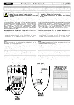
Sul retro del circuito stampato è disponibile un ponte stagno (PS1, vedi Fig.2).
Il regolatore standard deve essere alimentato 230V~50/60Hz (PS1 aperto).
Se il ponte viene stagnato (= PS2 chiuso), il regolatore funzionerà con alimentazione
24V~50/60Hz.
Come visibile in Fig. 1 i morsetti di alimentazione sono 5(N) e 6(L).
Nel caso di alimentazione a 230V~ è importante rispettare linea e neutro.
WIRINGS
This controller can be powered either with 230V~50/60Hz or with 24V~50/60Hz.
On the rear side of the printed circuit is available a tin jumper (PS1, see Fig.2).
The standard regulator must be powered 230V~50/60Hz (PS1 open).
If the bridge is tinned (= PS2 closed), the controller will operate with 24V~50/60Hz
power supply.
As can be seen in Fig. 1 supply terminals are 5(N) and 6(L).
If you have a 230V~ power supply, the live and neutral must be respected.
Sul retro del circuito stampato sono disponibili 4 piazzole di ingresso (vedi Fig.2) per la
realizzazione di configurazioni Speciali/Particolari:
M13 E/I,
ingresso per la selezione raffrescamento/riscaldamento centralizzata. Nel
caso non si usi la selezione raffrescamento/riscaldamento centralizzata si può usare
questo ingresso per attivare la modalità “Economy”.
M14 ECO,
ingresso per attivare la modalità “Economy”
M15 CF,
per collegare un “Contatto Finestra”
M16 COM CF,
comune, per collegare un “Contatto Finestra”
On the rear side of the printed circuit are available 4 input pitches (see Fig.2) for the
realization of Special/Particular configurations:
M13 E/I
, input for central heating/cooling selection. If not in use the central
heating/cooling, this input can be used to activate the "Economy" mode.
M14 ECO
, input to activate the "Economy" mode
M15 CF
, to connect the "Window Contact”
M16 COM CF
, common, to connect the "Window Contact”
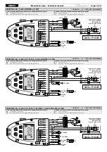
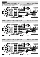
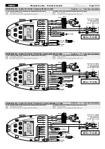
Eseguire i collegamenti elettrici seguendo lo schema di collegamento CBE25-A…
(possibili varianti CBE25-A001…A009).
Perform the electrical connections following the connection diagram CBE25-A…
(possible variants CBE25-A001…A009).
Nota
: ci sono delle limitazioni per l’uso del contatto finestra, leggere attentamente il
paragrafo “ATTENZIONE”.
La funzione associata agli ingressi delle piazzole M13/EI, M14/RDC-ECO e M15-M16/CF
può essere modificata nei parametri
C14
,
C15
e
C16
.
I segnali alle piazzole M13/EI e M14/RDC-ECO possono essere collegati alle piazzole
M13/EI e M14/RDC-ECO di altri termostati presenti nello stesso edificio (funzione E/I
centralizzata).
Tramite il connettore
RS
è possibile collegare una sonda di temperatura ambiente esterna.
I morsetti 11 e 12 sono un ingresso a cui è possibile collegare tipi diversi di sonda per
realizzare funzioni speciali: può essere collegata una sonda temperatura di mandata
(SND-W4) per realizzare la funzione di “changeover“ e/o “termostato di minima”; oppure
può essere collegato un termostato bimetallico (TM-32, TM-42)con funzione di “termostato
di minima”. Agendo sulla configurazione si sceglie quale tipo di sonda si intende usare.
Questo dispositivo è adatto a controllare la velocità dei ventilatori dei fan-coil a tre
velocità. La selezione delle velocità è effettuata tramite tre relè le cui uscite sono
disponibili ai morsetti 1, 2 e 3. Il morsetto 4 è il comune dei relè. In Fig. 1 è visibile come
collegare il ventilatore.
Le uscite per il ventilatore, morsetti da 1 a 4, sono libere da tensione e isolate rispetto
al resto del termostato. E’ quindi possibile alimentare il termostato a bassa tensione
SELV (24V~) e contemporaneamente pilotare un ventilatore ad alta tensione (230V~).
In questo caso è necessario mantenere una separazione tra i cavi SELV 24V~ e 230V~
nel rispetto delle norme vigenti. In particolare è necessario fissare i gruppi di cavi con
delle fascette separando i fili SELV dagli altri per evitare che se un filo si disconnette
accidentalmente questo non riduca l’isolamento verso SELV.
Note
: there are limitations for window contact use. Carefully read the paragraph
“ATTENTION”.
The function of the input
pitches
M13/EI, M14/RDC-ECO and M15-M16/CF can be
changed, through parameters
C14
,
C15
and
C16
.
Signals to
pitches
M13/EI and M14/RDC-ECO can be connected
pitches
M13/EI and
M14/RDC-ECO of other thermostats in the same building (centralised Heating/Cooling
function).
RS
connector can be used to connect an external room temperature sensor.
Terminals 11 and 12 is an input to connect different types of sensors for special
functions: connect a delivery temperature sensor (SND-W4) for the “changeover“
and/or “cut-off thermostat” function, or connect a bimetal thermostat (TM-32, TM-42)
with “cut-off thermostat” function. Change configuration to select which type of
sensor to use.
This device is suitable to control the fan speed of a 3-speed fan motor. The speed
selection is done through three relays, which outputs are available on terminals 1, 2
and 3. 4 is the common terminal of the relays. Fig 1 shows how to wire the fan motor.
Fan outputs from terminals 1 to 4, are voltage free contacts and are isolated towards
the other thermostat circuits. Therefore, a thermostat can be supplied with SELV low
voltage (24V~), while controlling a high voltage fan (230V~).
In this case, 24V~ SELV and 230V~ cables must be separated in accordance with
current standards. In particular, it is necessary to secure the two groups of cables with
cable ties separating the SELV wires from the others. This is required to avoid that the
insulation to SELV is reduced in the event of a wire accidentally disconnects.
Summary of Contents for CBE25
Page 18: ......


