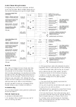
Control Mode Wiring Procedure
If integrating this unit with an Actionpac damper
control system (LNS, EMS or EMB) please refer to
the relevant catalogue and specific project details.
General
One metre of halogen free low smoke and fume
electric cable is fitted to each control mode for
convenience of on-site wiring. This provides the
distinct safety advantage of all electrics terminating
outside the duct, eliminating potential in-duct fire
hazards from wiring faults. The Electrical Thermal
Release is pre-wired with 0.5m halogen free low
smoke and fume cabling to Control Modes 5 and 6.
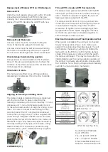
A Manual test switch fitted on the ETR allows
periodic operation of damper, simulating actual
fail safe release under smoke/fire conditions.
Commissioning
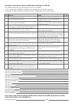
The procedure detailed under periodic maintenance
should be followed
Periodic maintenance
As detailed in BS 9999:2008
1. For dampers this is at least once per year for
units with spring operation.
2. Units operating in dusty atmospheres should be
frequently often to suit the severity of the conditions.
3. Units associated with systems may be required
to be checked, as part of the system, as often
as once per week or month to ensure ongoing
confidence in the life safety system. This may
be seen as analogous to fire alarm systems.
Procedure
1. The units should be carefully inspected and
cleaned of dust and debris
2) The units should then be lubricated with a light oil,
by wiping this over all the surfaces
3) Modes should be operated to ensure that it moves
the blades from open to closed and the reverse.
4) If the end switches (in the mode) are being used,
it should be checked that they are actually indicating
that the blades are open or closed. This is done
by running a cycle and checking both the blades
(open and closed) and the indication that the micro
switches are feeding back to.


