3
20210408 - LNNN00354 (3.0) Swegon reserves the right to alter specifications.
Actionair DWFX-F Installation Guide
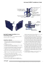
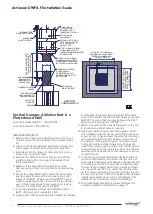
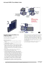
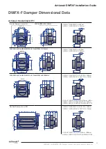
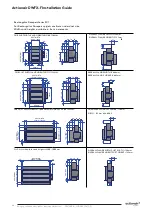
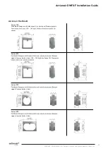
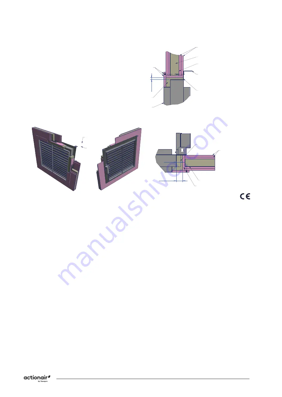
Vertical Damper Installation in a
Plasterboard Wall
Actionair SmokeShield PTC - [AA/F13069], [AA/F10704]
Actionair FireShield - [AA/F10705]
Installation Method
1. Measure the overall Fire damper casing size w x h, but
for Smoke Shield include the PTC Shroud (28mm) in
the width but do not include any of the peripheral
flange.
2. Calculate the hole size...
3.
For Fire Shield calculate the finished hole size by adding
10-40mm to the case width and height.
4.
For Smoke Shield calculate the finished hole size adding
10-52mm to the width and 10-40mm to the height.
5. Calculate the hole to cut size by adding two board
thicknesses to the finished hole width and height.
6. Mark out the hole on the partition and cut it out, cut-
ting the top and bottom edges first to maintain stabi
-
lity.
7.
Frame out the hole with stud and track and cover this
with board. Finish edges with joint filler.
8.
Drill clearance holes in the damper flange at 150mm
centres and such that they will allow screws to pull into
the stud and track around the hole.
9.
Install the damper and fasten.
10.
Back fill with mineral/stone wool and pattress over
this down to the spigot. Fasten with drywall screws at
Comments:
Rev:
Drawn By:
M.Bushell
Approved By:
A. Hill
1 of 1
Reference No:
S. Gore
Date:
Date:
By:
Date:
10/02/2020
28/01/2020
10/02/2020
Date:
A
Checked By:
Sheet
Rev
AAF13069
Description:
If your proposed installation details differ from
that shown here, please discuss this with the
Building Control Authority (BCA), referencing
this documentation, associated fire tests,
assessments, and other documentation shown
below. Deviation from this drawing requires
the approval of the relevant authority.
Installation Detail
Connecting ductwork omitted for clarity.
Ductwork must be independently supported.
There must be an appropriate break-away joint
between the damper and connecting ductwork
on both sides of assembly. Aluminium rivets or
plastic cleats, clips, clamps and bolts etc.
should be used for this, unless fire resisting
ductwork is being used where fire resisting
fixings should be used. A minimum of 200mm
between fire dampers installed in separate
ducts and 75mm between fire damper and a
construction element (wall/floor).
³
³
Applicable Test Report to
BS EN1366-2:
P112628-1011
BRE 256493
MINUTES
ES 120
Fire Resistance Integrity
and Leakage
A
ECN1975
MJB 10-02-20
Damper Size Range (mm)
VERTICAL APPLICATION
SMOKE SHIELD DWFX-F
IN PLASTERBOARD WALL,
OPTION 2
200 x 200 to 1000 x 1000
© Swegon Air Management Limited
South Street, Whitstable, Kent CT5 3DU
Tel: +44 (0)1227 276100
Fax: +44 (0)1227 264262
www.swegonair.co.uk
300mm centres such that they will allow screws to pull
into the stud and track around the hole.
11. Connecting ductwork omitted for clarity. Ductwork
must be independently supported. There must be an
appropriate break-away joint between the damper and
connecting ductwork on both sides of assembly. Alu-
minium rivets or plastic cleats, clips, clamps and bolts
etc. should be used for this, unless fire resisting duct
-
work is being used where fire resisting fixings should
be used. A minimum of 200 mm between fire dam
-
pers installed in separate ducts and 75 mm between
fire damper and a construction element (wall/floor).
12. Alternative partition systems to those shown within
this installation manual can be used if they have been
shown by test to have at least the same fire resistance
when tested to BS EN 1364-1:1999 as is required of
the damper. If the partition system has been success-
fully tested without stone mineral wool it does not
have to be used in practice when only considering the
fire performance of the complete system. The mineral
wool may still be needed for other reasons e.g. acous-
tic performance.
13. For SmokeShield installations, please reference the
actuator installation information on page 11.


