7
20210408 - LNNN00354 (3.0) Swegon reserves the right to alter specifications.
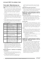
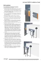
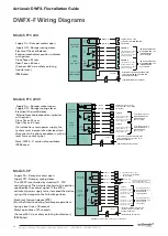
Actionair DWFX-F Installation Guide
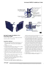
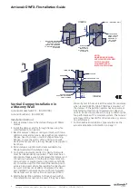
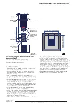
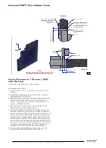
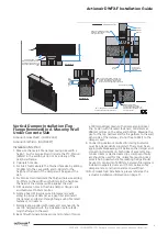
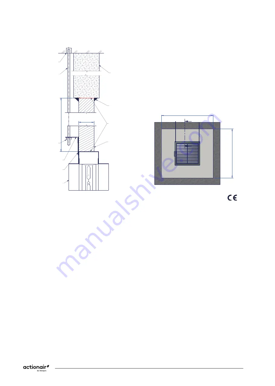
Vertical Damper, Ablative Batt in a
Masonry Wall
Actionair SmokeShield PTC - [AA/F10712]
Actionair FireShield - [AA/F10713]
Installation Method
1.
Rivet steel duct (by others) to damper spigot on non-
access side, using steel rivets.
2. Suspend the damper from the ceiling, using 10mm
studding drop rods, and support the damper from
lateral movement.
3. Make sure the area within the aperture and the
damper casing is free from any debris and remove any
dust.
4. Where the coated BATT will contact the surrounding
aperture apply Rockwool Fire pro glue to the outer
edges of the BATT. Where two coated BATTS are in
contact, use Rockwool fire pro glue as the joint adhe
-
sive. In both cases ensure that an even cover is achie-
ved over the entire thickness of the BATT.
5.
Continue installation of Rockwool ablative coated
BATT, until aperture is completely filled.
6.
Apply a bead of Rockwool acoustic intumescent sealant
to both sides of the wall, approximately 15mm wide
around perimeter of the aperture between wall and
BATT, ensuring that any gaps between the BATT and
surrounding edges are fully filled.
7.
Allow 12 hours for BATT penetration seal to cure prior
Comments:
Rev:
Drawn By:
S.Wehrle
Approved By:
A. Hill
1 of 1
Reference No:
S. Gore
Date:
Date:
By:
Date:
25/11/2019
15/07/2010
25/11/2019
Date:
H
Checked By:
Sheet
Rev
AAF10712
Description:
If your proposed installation details differ from
that shown here, please discuss this with the
Building Control Authority (BCA), referencing
this documentation, associated fire tests,
assessments, and other documentation shown
below. Deviation from this drawing requires
the approval of the relevant authority.
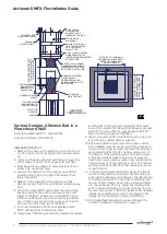
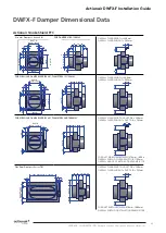
Installation Detail
Connecting ductwork omitted for clarity.
Ductwork must be independently supported.
There must be an appropriate break-away joint
between the damper and connecting ductwork
on both sides of assembly. Aluminium rivets or
plastic cleats, clips, clamps and bolts etc.
should be used for this, unless fire resisting
ductwork is being used where fire resisting
fixings should be used. A minimum of 200 mm
between fire dampers installed in separate
ducts and 75 mm between fire damper and a
construction element (wall/floor).
IF YOUR PROPOSED
INSTALLATION DETAIL DIFFERS
FROM THAT SHOWN, YOU MUST
DISCUSS THIS WITH THE
BUILDING CONTROL AUTHORITY
(BCA), REFERENCING THIS
DOCUMENT AND THE
ASSOCIATED FIRE TESTS,
ASSESSMENTS AND OTHER
DOCUMENTS SHOWN BELOW.
DEVIATION FROM THIS DRAWING
REQUIRES THE APPROVAL OF
THE RELEVANT AUTHORITY.
© Swegon Air Management Limited
South Street, Whitstable, Kent CT5 3DU
Tel: +44 (0)1227 276100
Fax: +44 (0)1227 264262
www.swegonair.co.uk
Applicable Test Report to
BS EN1366-2:
APPLUS 19/20747-1925
MINUTES
ES120
Fire Resistance
Integrity and Leakage
E
EC1770
MJB 20-02-18
Damper Size Range (mm)
VERTICAL APPLICATION
SMOKE DWFX-F &
ABLATIVE BATT
200 x 200 to 1000 x 1000
VERTICAL BLADES;
Damper can be installed with the blades in the
vertical orientation with actuator mounted at
either the top or bottom. For cleat locations of
motors mounted on top refer to drawing
F
EC1830
RTC 20/03/18
G
EC1839
RTC 13/04/18
CHANGE IN PROGRESS
See Mark Bushell
H
ECN1959
MJB 26-11-19
to removing any lateral damper supports.
8. Connecting ductwork omitted for clarity. Ductwork
must be independently supported. There must be an
appropriate break-away joint between the damper and
connecting ductwork on both sides of assembly. Alu-
minium rivets or plastic cleats, clips, clamps and bolts
etc. should be used for this, unless fire resisting duct-
work is being used where fire resisting fixings should
be used. A minimum of 200 mm between fire dampers
installed in separate ducts and 75 mm between fire
damper and a construction element (wall/floor).
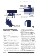
9.
For SmokeShield installations, please reference the
actuator installation information on page 11.


