background image


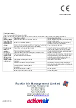
Troubleshooting 

Product Commissioning & Maintenance Available 
Below is a quick guide to problems that may be encountered. Please note modifications made to units will invalidate warranties etc


Fault 

Possible problem 

Recommended action 

Interface Mode 
Assembly does 
not fit into the 
shroud on the 
damper. 

Damper drive shaft not in line with  shroud. 

Gentle  adjustment made by manually setting 
blades to fully closed. 

Mode not in released position. 

Release clutch on motor using manual key. 
Check the slot on rear of interface. 

Slots on the non-access side of the  shroud may be blocked 
(due to removal of transit plate prior to backfilling). 

Ensure adequate clearance. 
 

Control mode 
does not 
operate 
electrically. 

The ETR is not correctly fitted to duct. 

Screw fix to duct ensuring both parts of the 
ETR are fully together. Do not over tighten. 

The mode is incorrectly wired. 

Check wiring in accordance with procedures. 

The ETR cables have been damaged or tampered with. 

Replace with new mode. 

Control Mode 
operates, but 
limited, or no 
movement of 
damper blades 
is observed. 


The mode is not correctly 
synchronised with the interface. 

Remove motor from interface. Check motor in 
fully released state. Set position of interface, 
and refit motor with label upmost, include 
motor location pointer and washer. 

The damper is damaged or poorly 
installed. 

New damper or re-install. 

Interface not fitted correctly to damper 

Fit interface correctly, ensure retaining pin 
protrudes through location hole in the shroud. 

Foreign matter is impeding blade 
movement. 

Check and remove. 

Motor location pointer omitted. 

Fit new pointer. 

Mode not screwed down correctly. 

Check and tighten. 

Ruskin Air Management Limited 

South Street, Whitstable, Kent 

CT5 3DU England. 

Tel: 01227 276100 

Fax: 01227 264262 

Email: sales@actionair.co.uk 

Website: 

www.actionair.co.uk


 LNNN00357 (B) 


0832-CPR-P0002


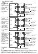
Summary of Contents for SmokeShield PTC

Page 1: ...ion for the Electrical Thermal Release ETR to be mounted through the ductwork Ideally this should be in the top half of the duct and or above the level of the interface Apply the self adhesive template located on the rear of the ETR and drill the necessary holes Ø3mm Ø9 5 Ø11mm Push the ETR through the duct and ensure that both screws are used to hold it in position Both screws should be tightened...

Page 2: ...TF 72 C AC 250V 6 3 A BROWN BLUE 1 2 3 4 5 6 L1 SUPPLY 230V AC 50 60Hz TYPICALLY 12W MOTORING 4W RESET COMMON COMMON VOLT FREE CONTACT MADE BETWEEN 1 2 WHEN DAMPER FULLY RELEASED VOLT FREE CONTACT MADE BETWEEN 4 6 WHEN DAMPER FULLY RESET M AC DC 24V 50 60 Hz 14 VA 12 4 W 30 C 50 C CONTINUOUS ELECTRICAL THERMAL RELEASE ETR MUST BE FITTED TO DUCTING FOR DAMPER OPERATION SPRING BIASED TEST SWITCH TF ...

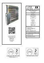
Page 3: ...010 SMOKE SHIELD PTC LEAKAGE RATED SS I F E120 ve ho i o S SS DWFX C SS DWFX F SS OSW E120 ve i o S SS S A E120 ve i o S E120 ho i o E90 ho i o S Sensing element Response temperature 72 C Load Bearing capacity N A Closure times M5 6 22s tamb 20 C M5 3P 16s tamb 20 C Corrosion tested to En 60068 2 52 Pass Operational reliability 20 000 cycles Pass Ambient leakage test Pass LPS 1162 Issue 4 Cert No ...

Page 4: ...ot over tighten The mode is incorrectly wired Check wiring in accordance with procedures The ETR cables have been damaged or tampered with Replace with new mode Control Mode operates but limited or no movement of damper blades is observed The mode is not correctly synchronised with the interface Remove motor from interface Check motor in fully released state Set position of interface and refit mot...

Reviews: