background image

8

Active Research Ltd 2022

NMEA 0183 Talker and Listener Designations

• 

The NMEA have updated the NMEA 0183 specifications to ensure a consistent naming conven

-

tion is used for labelling ports. The designation follows the same rules as used for Rx and Tx 

labelling but uses the terminology “Talker” and “Listener” instead.

•  The 

Input / Receiving (Rx) port

 will be labelled as a 

LISTENER


port.

•  The 

Output / Transmitting(Tx) port

 will be labelled as a 

TALKER

 port.

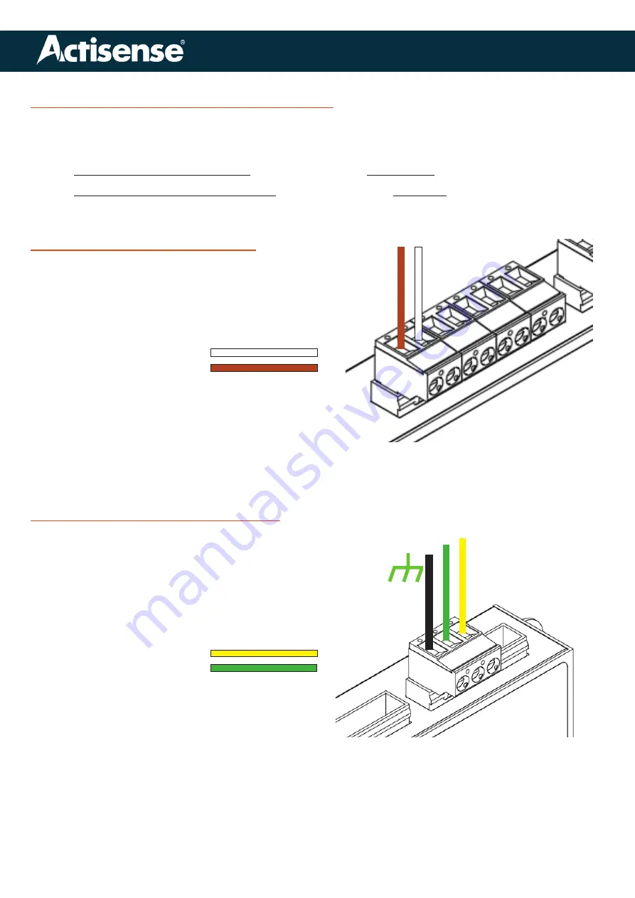
NMEA “Talker” Input Connections

The PRO-NDC-1E has 5 input connections, labelled 

IN-1 to  IN-5.

• 

Inputs are labelled ‘A’ and ‘B’ in line with the NMEA 

specification for labelling NMEA0183 signal pairs.

•  If your “talker” follows the NMEA wire colour con-

vention, the wires should be coloured as follows:

• 

TALKER ‘A’/+   : WHITE

• 

TALKER ‘B’/-  

: BROWN

•  If your wire colours do not follow the NMEA 

convention, you will need to consult your device 

manual and find which wire colours corrrespond 

to ‘A’/+ and ‘B’/- and attach accordingly.

• 

If your “talker” device has only ‘A’ and ‘GND’ output 

wires, connect the ‘GND’ wire to ‘B’/-

‘A’/+

‘B’/-

NMEA “Listener” Output Connections

The PRO-NDC-1E has 2 output connections, labelled 

OUT-1 & OUT-2.

• 

Outputs are labelled ‘A’ and ‘B’ in line with the 

NMEA specification for labelling NMEA0183 sig

-

nal pairs.

•  If your “listener” follows the NMEA wire colour 

convention, the wires should be coloured as fol

-

lows:

• 

LISTENER ‘A’/+   : YELLOW

• 

LISTENER ‘B’/-   : GREEN

•  If your wire colours do not follow the NMEA 

convention, you will need to consult your device 

manual and find which wire colours correspond to 

‘A’/+ and ‘B’/- and attach accordingly.

•  The shield from each listener should be connect-

ed to the ‘GND’ connector on the output terminal.

•  The RF ground stud should be connected to the 

vessels RF ground plate using a minimum con-

ductor size of 8 AWG in accordance with the 

NMEA 0400 installation standard. Use a crimped 

connector to securely bond the RF wire. 

‘B’/- ‘A’/+

Summary of Contents for PRO-NDC-1E

Page 1: ...1 Active Research Ltd 2022 Connect without limits Professional Type Approved NMEA 0183 Multiplexer Install User Manual Issue 1 0...

Page 2: ...ot accept any liability for differences between the product and this document To check for updated information and specifications please check www actisense com Active Research Ltd will not be liable...

Page 3: ...NMEA wire colour coding 5 Terminal Connections 6 Powering the PRO NDC 1 6 Serial Port Connections 7 Ethernet Connection 7 RF Ground connection 7 NMEA Talker Connections 8 NMEA Listener Port Connection...

Page 4: ...still remains the responsibility of the NMEA Talker that generated the data Warning 2 Installation and Operation This product must be installed and operated in accordance with the instructions provid...

Page 5: ...dication via web tool Designed for 12 and 24 Volt supply Pluggable connector system supports both screw and screwless terminals Double Galvanic isolation between all inputs and outputs Galvanic isolat...

Page 6: ...n 10 to 35 Volts DC The PRO NDC 1E terminal should be connect ed to the vessel power supply terminal via the correctly rated fuse in accordance with the NMEA 0400 installation standard The PRO NDC 1E...

Page 7: ...adaptor which contains a USB SERIAL converter with the necessary Rx Tx and GND connections Ethernet Connection An Ethernet port is provided as a means of cor rectly configuring your PRO NDC 1E Use ei...

Page 8: ...u will need to consult your device manual and find which wire colours corrrespond to A and B and attach accordingly If your talker device has only A and GND output wires connect the GND wire to B A B...

Page 9: ...ction or basic ethernet networks If the PRO NDC 1E is connected directly to a PC or the ethernet network does not have a DHCP server the PRO NDC 1E will communicate using the auto IP by default A stan...

Page 10: ...your PC and open the Network Status menu In the Network Status menu under Advanced Network Settings select Change Adapter Options Right click on your Local Connection and select Properties Select Int...

Page 11: ...der the General tab in Properties make sure that Obtain an IP address automatically is selected Obtain DNS server address automatically is selected Under the Alternate Configuration tab make sure that...

Page 12: ...lashing solid Flashes at a rate determined by baud rate and data length If available bandwidth is nearly full LED may appear solid instead of flashing None required STATUS Red Flashing solid Buffer Fu...

Page 13: ...35 V to 35 V short term 1 second Listener Input Protection Current limited overdrive protection to 40 VDC and ESD protection Listener Data Indicator LED Green Flashes with data rate Connectors Plugga...

Page 14: ...Dimensions 139mm W x 98mm H x 26mm D Weight 360g Mounting Bulkhead mount or DIN rail mount DIN kit 1 Approvals and Certifications EMC IEC 60945 2002 08 DNVGL CG 0339 2019 IACS UR E10 Rev7 Compass Safe...

Page 15: ...nical Support to help trace the issue before considering the return of the product If the Actisense support engineer concludes that the PRO NDC 1E unit should be returned to Acti sense a Return Mercha...

Page 16: ...16 Active Research Ltd 2022 Active Research Ltd 21 Harwell Road Poole Dorset UK BH17 0GE Telephone 44 0 1202 746682 Email sales actisense com Web www actisense com Connect without limits...

Reviews: