background image

Technical manual

StepArray

L ' a c o u s t i q u e   a c t i v e

Summary of Contents for SA100P

Page 1: ...manual L a c o u s t i q u e a c t i v e StepArray ...

Page 2: ...n set up 12 4 Column positionning rules 14 5 Options 16 6 SAdrive software 16 7 CAD modeling 17 References 18 II StepArray technical reference 20 8 Installation of the columns 21 9 Wiring 22 10 Test before powering up 25 11 SAdrive software 26 12 Advanced functions 27 13 Troubleshooting 30 14 Hardware specifications 32 15 Acoustical data 37 List of Tables 44 List of Figures 44 2 ...

Page 3: ... details about the StepArray system How to use this manual This reference manual is divided in two parts The first part is a tutorial for recommandation It deals with StepArray design and principles introducing the acoustic background necessary to understand sound reinforcement in large space and how StepArray can help to achieve good intelligibility in these places The second part is a technical ...

Page 4: ...tepArray system 9 2 1 StepArray system example 10 2 2 StepArray column models 11 2 3 StepArray specificity shared electronics 11 3 Choosing the right installation set up 12 3 1 Columns 12 3 2 Processors 13 3 3 Amplifiers 13 3 4 Cables 14 3 5 Subwoofers 14 4 Column positionning rules 14 5 Options 16 5 1 Microphone MIC 16 5 2 Sub bass Output SUB 16 5 3 Sound Security System SSS 16 6 SAdrive software...

Page 5: ...rge spaces Speech reinforcement in large and reverberant rooms is made difficult by several causes namely reverberation ambient noise and architectural constraints Reverberation In all rooms sound transmission from a loudspeaker to a listener can be divided in two parts figure 1 Direct sound which depends on the loudspeaker to listener distance and on the loudspeaker directivity Reverberated sound...

Page 6: ...ant portion of the wall material and most of the time this is not possible Providing a strong signal to noise ratio is also important but it is not enough to ensure intelligibility Therefore in large and reverberant rooms the most important parameter the public address must affect is the Direct Sound Reverberated Sound ratio It is necessary to privilege the direct sound energy and avoid putting en...

Page 7: ...ly constant SPL over the audience using a large number of loudspeakers it is usually not able to provide satisfactory speech intelligibility when reverberation in the room is high In addition it usually has a rather negative impact on the visual aspect of the room In contrast high speech intelligibility can be obtained with a limited number of loudspeaker arrays often only 1 or 2 in a large and hi...

Page 8: ...ve front b In an electronic array loudspeakers are aligned vertically and the wave front is synthesized by adequate filtering by filters Fi de lays Di and gain Gi associated to each loudspeaker Figure 3 Electronic and geometric arrays 1 3 DGRC The StepArray system The StepArray columns implement the DGRC line array principle Digital and Geometric Radiation Control which is a synthesis of geometric...

Page 9: ...n make a big cost difference Power is uniformly distributed to all loudspeakers This way they can all be used at their maximum capabilities enhancing overall performance and sound pressure level The number of channels does not depend on the number of loudspeakers Therefore many small full range loudspeakers can be used to obtain perfect sound quality in the treble range and reduce secondary lobes ...

Page 10: ...ily accessed in the technical room Electronics can be placed in a fireproof room with uninterruptible power supply UPS The operating parameters of the UT26 processors are tuned with the SAdrive software through RS232 serial communication UT26 processors feature filtering functions such as the control of directivity equalization delay and high level functions In addition the StepArray system featur...

Page 11: ... areas whereas column whose name ends with a S are designed for tilted audience areas or with balcony 2 3 StepArray specificity shared electronics One of the advantages of using external electronics is that several columns can be connected via their amplifier to the same UT26 processor A UT26 processor features 6 analog symmetrical outputs Therefore a single UT26 processor can be used to deliver s...

Page 12: ...umns are available in standard RAL colors RAL9016 and RAL9005 but any other RAL color is available with the COL option Table 1 sums up these charac teristics Max SPL Hor opening Bandwidth Mounting Colors 95dBSP L 180 135Hz 17kHz 3dB Vertical White RAL9016 pink noise 6dB 110Hz 19kHz 10dB supplied Black RAL9005 in listening area square brackets Any RAL COL option Table 1 General characteristics of S...

Page 13: ...m 2 5m 2 1m Flat 0 5 35m 45m 1m 6 SA400P 4m 3 0m 2 6m Flat 0 3 68m 90m 1m 6 SA180S 1 8m 3 0m 2 6m Tilted 5 20 22m 29m 4m 3 SA250S 2 5m 4 2m 3 8m Tilted 5 20 28m 36m 4m 6 Table 2 Specific characteristics of StepArray column models 3 2 Processors The UT26 processor has 6 output channels therefore it can deliver signals for two 3 channel columns or one 6 channel column It is also possible to connect ...

Page 14: ...r fitted with the SUB option see section 5 2 Active Audio proposes subwoofers SA12 SW and SA12 SWA suitable for StepArray installations see section 14 3 4 Column positionning rules When choosing a StepArray setup the goals are Ensuring proper SPL coverage Delivering satisfying intelligibility of vocal messages Avoiding echoes and feedback effects Giving the feeling that the sound comes from the sp...

Page 15: ...lumns otherwise he will hear the echo of his own voice the audience must feel that the sound comes from the speaker This is achieved by fitting a column on each side of the stage so as to re centre the sound A single column can be used but in this case it has to be close to the zone to be covered Prevent the feedback effect there should never be a microphone aiming at a column this could generate ...

Page 16: ...ring is described in section 9 6 When using the SUB option the subwoofer signal is low pass filtered by the UT26 processor with a 4th order Linkwitz Riley type at 180 Hz and the column s signal is filtered with the complementary high pass filter Note that for speech diffusion there is no point extending the bass response 5 3 Sound Security System SSS The SSS option Sound Security System brings EN ...

Page 17: ...ctivity control block which allows the user to change the radiation pattern of StepArray columns in real time This block is presented in figure 13 Figure 13 SAdrive directivity block 7 CAD modeling There are powerful CAD software tools that can predict the acoustics of a room and accurately model the radiation of loudspeaker arrays These tools can calculate various acoustic index such as reverbera...

Page 18: ...Hz by column SA250S Simulation with EASE Figure 14 Examples of a CAD modeling results References DGRC Arrays X Meynial DGRC arrays A synthesis of geometric and electronic loudspeaker arrays AES 120th Convention Preprint 6786 Paris May 2006 C HEIL Sound Wave Guide US Patent 5 163 167 Inventor C Heil nov 10 1992 DSP directivity G W J van Beuningen E W Start Optimizing Directivity Properties of DSP C...

Page 19: ...Technical manual StepArray L a c o u s t i q u e a c t i v e ...

Page 20: ...ed functions 27 12 1 Automatic gain control AGC 27 12 2 Security Sound System SSS 28 12 3 Feedback killer 29 12 4 Remote control 30 13 Troubleshooting 30 14 Hardware specifications 32 14 1 UT26 processor characteristics 32 14 2 MPA6150 amplifier characteristics 33 14 3 Subwoofers characteristics 34 14 4 Columns characteristics 35 15 Acoustical data 37 15 1 Common data 37 15 2 SA100P acoustical dat...

Page 21: ...unting See also figure 25 on page 36 for technical drawings of the brackets Place the 2 brackets on the wall using 8mm diameter screws x3 x3 1 Column height 5mm 2 Ensure verticality 3 Mount the column using the supplied nut and screw 4 Figure 15 Column mounting on a wall It is important to ensure verticality when mounting StepArray columns Last update December 23 2010 21 ...

Page 22: ...WAGO UT26 MPA6150 MPA6150 b Daisy chain wiring Figure 16 UT26 to MPA6150 wiring XLR F to Wago cables use standard XLR wiring convention as shown in table 4 XLR Wago pin 1 Ground pin 2 pin pin 3 pin Table 4 XLR to Wago wiring 9 2 Amplifier setup MPA6150 amplifiers should be tuned with all gains to max and microswitches set for independent channels as described in figure 17 Set all microswitches for...

Page 23: ... 3 GND 1 Not Used 5 6 4 SA250P CH1 CH3 CH5 CH4 CH2 CH6 1 2 3 4 5 6 GND 6 channel column cabling on MPA6150 amplifier 6 channels Figure 18 MPA6150 to column wiring 9 4 Wiring the microphone MIC option The MIC option consists of a microphone integrated inside the column and a daughter board placed inside the UT26 processor which supplies phantom power on input 2 of the processor The microphone outpu...

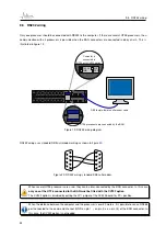
Page 24: ... diagram RS232 wiring uses standard DB9 null modem wiring as shown in figure 20 6 7 8 9 1 2 3 4 5 1 2 3 4 5 6 7 8 9 Figure 20 RS232 wiring standard DB9 null modem When several UT26 processors are used they can be inter connected by the BAN connector In this case only one of the UT26 connected to the BAN must be fitted with the CV232 option The CV232 option is disabled by putting the JP1 jumper of ...

Page 25: ...esistance of each channel of the column must be controlled at the end of the cable connected to the amplifier side The measured electrical resistances values must correspond to the values below Channel 1 2 3 4 5 6 SA100P 6 6Ω 6 6Ω 6 6Ω SA180P 6 6Ω 6 6Ω 6 6Ω SA250P 6 6Ω 6 6Ω 6 6Ω 4 4Ω 4 4Ω 4 4Ω SA400P 6 6Ω 6 6Ω 6 6Ω 6 6Ω 6 6Ω 6 6Ω SA180S 6 6Ω 6 6Ω 6 6Ω SA250S 3 3Ω 6 6Ω 6 6Ω 4 4Ω 4 4Ω 3 3Ω For detai...

Page 26: ...lization steps are described below 2 Log in administrator mode 4 Switch ON the processor connected with CV232 8 Save as boot setup to make all changes permanent 3 Connect to COM port 7 Set initial parameters for this processor then apply Repeat step 6 and 7 for each other processor Processor address must be unique 5 Set initial parameters for this processor then apply 1 Switch OFF all processors U...

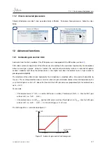
Page 27: ... noise is high in order to provide good intelligibility The amplitude of the ambiant noise captured by the microphone is smoothed with a time constant adjustable by the user This resulting smoothed value is used as a basis for gain calculation below a threshold adjustable by the user the AGC gain is set to 0dB above this threshold the AGC gain increases proportionally to the ambiant noise up to 12...

Page 28: ...l along with a current sensor to monitor effective current consumption of each channel of the system A UT26 processor equipped with the SSS option adds a high frequency sine component to the audio signal output and synchronously detects this high frequency signal on its analog input 2 where the SSS box is connected This loopback allows precise monitoring of the current consummed by the columns The...

Page 29: ...lfunctions a column channel is disconnected from the amplifier amplifier is off a gain on the amplifier was changed by mistake a loudspeaker burned the column cable is cut etc 12 3 Feedback killer The feedback killer used in the UT26 processors is a modulated delay The delay is modulated sinusoidally with a constant depth of 2 6ms while the modulation frequency is adjustable for more or less agres...

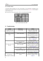
Page 30: ...nput signal detected Check that the Sig LED is ON in SAdrive s Status frame If the LED is OFF check that the Input threshold is not too high The UT26 processor is not inited Follow the steps presented in section 11 1 on page 26 to init processors with SAdrive SAdrive does find the UT26 processor The computer to UT26 cable is defective Check that RS232 cable is wired as described in section 9 5 on ...

Page 31: ...ituation see figure 9 on page 13 The column model in SAdrive doesn t match the real column model Correct the column model using the menu Active Setup Manage processors No bass signal on SUB output The SUB option has not been selected in SAdrive Check the SUB option using menu Active Setup Manage processors The AGC function is not accessible and the Noise field in the status frame shows The MIC opt...

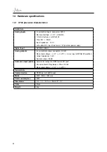
Page 32: ...gital input AES EBU 48kHz Analog outputs 6 symmetrical outputs connectors XLR M Max output voltage 1 6V 3 3dBU i e max input of MPA6150 amplifier Output impedance 46 Ω Dynamic range 95 dB Sub bass output option Symmetrical output on DB25 female BCL port 4th order Likwitz Riley lowpass filter at 180Hz Max output voltage 1 6V 3 3dBU General data Communication RS232 port at 38400 bauds Mains 230V 50H...

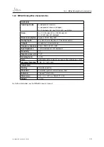
Page 33: ...enix connectors Outputs 6 outputs on screw terminals Frequency response 20Hz 20kHz 1W 1dB Input Impedance 10kΩunbalanced 20kΩ balanced Sensitivity 1Veff Signal to noise ratio 95dB Damping factor 300 Gain Adjustable with 6 knobs on rear panel Max voltage gain 28dB Harmonic Distortion THD 0 1 1kHz General data Cooling Variable speed fan Protection Protection against overload and overheat Indicators ...

Page 34: ...pedance 8Ω Amplification SA12 SW Compatible with MPA 6150 amplifier SA12 SWA Digital amplifier Class D Electrical connection7 Neutrik Powercon 195V 250V AC 50 60Hz Mechanical data Materials Plywood Dimensions 435 400 440mm Weight SA12 SW 18 5kg SA12 SWA 19 8kg Color Black Tuning and exploitation Software Supplied SAdrive software Filtering processor UT26 with SUB option 10 2 30 25 20 15 10 5 0 5 F...

Page 35: ... 6 6Ω 6 6Ω 4 4Ω 4 4Ω 4 4Ω SA400P 6 6Ω 6 6Ω 6 6Ω 6 6Ω 6 6Ω 6 6Ω SA180S 6 6Ω 6 6Ω 6 6Ω SA250S 3 3Ω 6 6Ω 6 6Ω 4 4Ω 4 4Ω 3 3Ω Table 9 DC resistance of StepArray columns For details on connector pin assignement see figure 18 on page 23 in section 9 3 14 4 2 Mechanical characteristics of StepArray columns W L D 34mm to 55mm Figure 24 StepArray column dimensions Last update December 23 2010 35 ...

Page 36: ...SA400P 4096 124 135 39kg 46kg 7G Table 10 Mechanical and electrical characteristics of StepArray columns More precise schematics are available on Active Audio s website in several formats http www activeaudio fr en gamme steparray catalogue et telechargements 14 4 3 Fixing brackets 121 51 5 ϕ11 25 25 96 51 35 65 82 89 34 42 11 ϕ8 5 11 11 11 71 22 M4 Red is bottom bracket only Figure 25 Fixing brac...

Page 37: ... 10 4 30 25 20 15 10 5 0 5 10 frequency Hz amplitude dB Figure 26 Frequency response column SA250P Average of the mesurements at 7 10 15 20 25 and 30m In red with bass high pass on position 100Hz in blue with bass high pass on position 200Hz 90 60 30 0 330 300 270 20dB 10dB 500Hz 1kHz 2kHz 4kHz 8kHz Figure 27 Horizontal directivity column SA250P Last update December 23 2010 37 ...

Page 38: ...0dB b SA100P horizontal directivity sound level for the voice octaves 500Hz 1kHz 2kHz on the listening plane 0 2 4 6 8 10 12 14 16 18 20 15 10 5 0 5 10 15 SPL dist SA100P 250Hz 500Hz 1000Hz 2000Hz 4000Hz 8000Hz c Sound level by octave in the axis of the listening plane in front of the column with respect to the distance from the column Figure 28 SA100P acoustical data 8 Column is in nominal positi...

Page 39: ...dB b SA180P horizontal directivity sound level for the voice octaves 500Hz 1kHz 2kHz on the listening plane 0 5 10 15 20 25 30 35 15 10 5 0 5 10 15 SPL dist SA180P 250Hz 500Hz 1000Hz 2000Hz 4000Hz 8000Hz c Sound level by octave in the axis of the listening plane in front of the column with respect to the distance from the column Figure 29 SA180P acoustical data 9 Column is in nominal position Leve...

Page 40: ...dB 10dB 15dB 20dB b SA250P horizontal directivity sound level for the voice octaves 500Hz 1kHz 2kHz on the listening plane 0 5 10 15 20 25 30 35 40 45 15 10 5 0 5 10 15 SPL dist SA250P 250Hz 500Hz 1000Hz 2000Hz 4000Hz 8000Hz c Sound level by octave in the axis of the listening plane in front of the column with respect to the distance from the column Figure 30 SA250P acoustical data 10 Column is in...

Page 41: ...dB 10dB 15dB 20dB b SA400P horizontal directivity sound level for the voice octaves 500Hz 1kHz 2kHz on the listening plane 0 10 20 30 40 50 60 70 15 10 5 0 5 10 15 SPL dist SA400P 250Hz 500Hz 1000Hz 2000Hz 4000Hz 8000Hz c Sound level by octave in the axis of the listening plane in front of the column with respect to the distance from the column Figure 31 SA400P acoustical data 11 Column is in nomi...

Page 42: ...0dB 15dB 20dB b SA180S horizontal directivity sound level for the voice octaves 500Hz 1kHz 2kHz on the listening plane 0 5 10 15 20 25 15 10 5 0 5 10 15 SPL dist SA180S 250Hz 500Hz 1000Hz 2000Hz 4000Hz 8000Hz c Sound level by octave in the axis of the listening plane in front of the column with respect to the distance from the column Figure 32 SA180S acoustical data 12 Column is in nominal positio...

Page 43: ...SA250S horizontal directivity sound level for the voice octaves 500Hz 1kHz 2kHz on the listening plane 0 5 10 15 20 25 30 15 10 5 0 5 10 15 SPL dist SA250S 250Hz 500Hz 1000Hz 2000Hz 4000Hz 8000Hz c Sound level by octave in the axis of the listening plane in front of the column with respect to the distance from the column Figure 33 SA250S acoustical data 13 Column is in nominal position Levels are ...

Page 44: ...s speech intelligibility reverberated sound impairs it 5 2 J shape wave front 7 3 Electronic and geometric arrays 8 4 DGRC principle 9 5 Example of StepArray system 10 6 Listening zones P models 11 7 Listening zones S models 11 8 Shared electronics example 12 9 Listening area definition 13 10 Interferences between columns 15 11 Rear panel of the UT26 processor 16 12 Synoptic frame 17 13 SAdrive di...

Page 45: ... 35 25 Fixing brackets for wall mounting of StepArray columns 36 26 Frequency response column SA250P 37 27 Horizontal directivity column SA250P 37 28 SA100P acoustical data 38 29 SA180P acoustical data 39 30 SA250P acoustical data 40 31 SA400P acoustical data 41 32 SA180S acoustical data 42 33 SA250S acoustical data 43 Last update December 23 2010 45 ...

Page 46: ...www activeaudio fr 332 Bd Marcel Paul CP602 44806 Saint Herblain Cedex France Tel 33 0 2 40 92 39 90 Fax 33 0 2 40 92 39 91 Contact ...

Reviews: