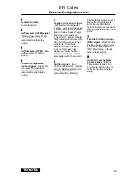
17
TCCS-L
(Toyota Computer Control System - Later version)
1) Complete ALL steps in Section 4,
“Vehicle Preparation”
2) Access Computer Test Connector
Rectangular type:
• Open hinged cover on connector.
• Some connectors use a special
grease on the contacts to prevent
corrosion. Do not wipe off!
Circular type:
• Remove the protective rubber cap
from the connector.
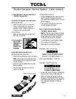
3) Turn ignition
Key to ON
Position but
DO NOT
START THE
ENGINE.
4) Install Code Scanning Tool
Rectangular test connector:
• Plug code scanner tool into connector.
Note: Tool does not completely cover
all contacts in 24 pin type connector.
This is normal.
• The tool only fits ONE WAY into the
test connector
• The tool will
not harm the vehicle
engine computer.
O
FF
ON
TM
T
O
Y
O
T
A
CP9025
Remove cap if present
Circular test connector:
• Plug the black jumper wire into both
test connector contacts. (Service
manuals refer to these as the “T” and
“E” terminals.)
• The jumper wire will
not harm the
vehicle engine computer.
5) Get Codes from the Flashing
“CHECK” Engine Light
• NOTE: If no trouble codes are stored,
the light will rapidly flash (about four
times a second). This means the
computer has found no problem.
• Count flashes to get trouble codes.
• All codes are 2 digits long.
• Each digit is a group of flashes.
Example: code 12 looks like...
❊
PAUSE
❊❊
FLASH (pause) FLASH FLASH
(FLASH = 1, FLASH FLASH = 2.
Put 1 and 2 together = code 12.)
Example: code 23 looks like...
❊❊
PAUSE
❊❊❊
FLASH FLASH (pause)
FLASH FLASH FLASH
• Codes are sent in numeric order from
the lowest number to the highest.
• After all codes are sent, the whole
sequence is repeated. This continues
until the ignition key is turned OFF or
the code scanning tool is discon-
nected.
TOYOTA
Summary of Contents for Code Scanner CP9025
Page 49: ...49 NISSAN...


