12
13
Buick
Tuar Company
Post Offi
ce Box 354
Flint, MI 48501
Oldsmobile
Lansing Lithographers
Post Offi
ce Box 23188
Lansing, MI 48909
Cadillac, Chevrolet, Pontiac
Helm Incorporated
Post Offi
ce Box 07130
Detroit, MI 48207
OTRAS FUENTES-Privadas
American Motors Corporation
Myriad
8835 General Drive
Plymouth Township, MI 48170
Chrysler Corporation
Dyment Distribution Service
Service Publication
20770 Westwood Drive
Strongsville, OH 44136
Ford Publications Department
Helm Incorporated
Post Offi
ce Box 07150
Detroit, MI 48207
MANUAL DEL VEHICULO, FUENTES DE INFORMACION ACERCA DE SERVICIO.
La siguiente es una lista de editores que publican manuales de servicio para vehículos específi cos a por
un precio nominal.
Escribirles para averiguar la disponibilidad y precios, especifi cando la marca, estilo y año del modelo del
vehículo.
Automóviles norteamericanos y
extranjeros
Chilton Book Company
Chilton Way
Radnor, PA 19089
Cordura Publications
Mitchell Manuals, Inc.
Post Offi
ce Box 26260
San Diego, CA. 92126
Motor’s Auto Repair Manual
Hearst Company
250 W. 55th Street
New York, NY 10019
IMPORTANTE
ESTE MANUAL PRESENTA LAS INSTRUCCIONES COMPLETAS PARA LA CON-
EXION DEL ANALIZADOR DE VIBRACIONES DEL MOTOR. ADEMAS DESCRIBE
MUCHAS DE LAS PRUEBAS QUE ESTE INSTRUMENTO ES CAPAZ DE REALI-
ZAR COMO ASIMISMO CUANDO SE DEBEN USAR EN BASE AL RENDIMIENTO
DEL VEHICULO, PUESTA A PUNTO DEL MOTOR O PROBLEMA ENCONTRADO.
CONSULTAR EL MANUAL DE SERVICIO DEL VEHICULO PARA LA INFORMACION
ESPECIFICA DE LA PUESTA A PUNTO Y LOS PROCEDIMIENTOS DE PRUEBA.
SEGUIR LAS ESPECIFICACIONES DEL FABRICANTE Y LOS PROCEDIMIENTOS
DE PRUEBA PARA AJUSTAR EL ANGULO DE CIERRE Y LA VELOCIDAD EN VACIO
(RALENTI), ESPECIALMENTE EN VEHICULOS CON ENCENDIDO ELECTRONICO Y
CONTROLES DE EMISION MODERNOS. NO TRATAR DE REPARAR UN VEHICULO
SIN TENER LAS INSTRUCCIONES Y ESPECIFICACIONES DEL FABRICANTE.
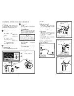
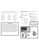
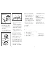
Fig. 1
Diagrama de conexiones prin-
cipales
DISTRIBUIDOR
BAT.
VERDE
NEGRO
CONTROLES, CONEXIONES Y ACCESORIOS DEL ANGULO DE CIERRE/
TACOMETRO/VOLTIMETRO
DESCRIPCION
El ángulo de cierre/tacómetro/voltímetro modelo
CP7605 tiene un interruptor y medidor claramente
rotulados como se muestra en el diagrama de con-
exiones principal, fi gura 1 a continuación.
1 MEDIDOR
Este medidor indica las escalas siguientes:
•
Voltios
0-16
• RPM
0-2000 (8 cilindros)
0-4000 (4 cilindros - multiplicar la
escala de 8 cilindros por 2)
• RPM
0-2500 (6 cilindros)
• Angulo de cierre 0-45 grados (8 cilindros)
0-90 grados (4 cilindros -
multiplicar la escala de 8
cilindros por 2)
• Angulo de cierre 0-60 grados (6 cilindros)
•
Platinos
Correctos/Defectuosos
2 SELECTOR DE FUNCION
Este selecciona las funciones de RPM, ángulo de
cierre o voltios del instrumento.
3 CONDUCTOR DE PRUEBA
Conectar este conductor al punto de prueba
correcto en el vehículo para efectuar las prue-
bas según se requiera y describen más abajo.
MEDICIONES
DE
VOLTAJE
PINZA VERDE - Conectar la fuente de voltaje
positivo (+) que se va a medir. (Borne + de la
batería, terminal de salida del alternador, recep-
táculo de bombilla, etc.).
PINZA NEGRA - Puesta a tierra del vehículo.
¡PRECAUCION!
Evitar conectar la PINZA NEGRA al borne negativo
(-) de la batería o a cualquier componente del
sistema de combustible, ya que si llegaran a
haber gases presenten podrían explotar debido a
las chispas producidas al hacer las conexiones.
DISTRIBUIDOR O
TACOMETRO
BOBINA
TIERRA DEL
MOTOR

