250V MAX
15A MAX
FUSED
COM
DC
15A
20M
200
K
20K
2K
200
8CYL
6CYL
TACH
X10
5CYL
4CYL
8CYL
OHMS
15
A
22
Ignition System Wires
This test measures the resistance of spark
plug and coil tower wires while they are being
flexed. This test can be used for distributorless
ignition systems (DIS) provided the system
does not mount the ignition coil directly on the
spark plug.
Test Procedure:
1. Remove ignition system wires one at a
time from engine.
• Always grasp ignition system wires on
the boot when removing.
• Twist the boots about a half turn while
pulling gently to remove them.
• Refer to vehicle service manual for igni-
tion wire removal procedure.
• Inspect ignition wires for cracks, chaffed
insulation, and corroded ends.
NOTE: Some Chrysler products use a
“positive-locking” terminal electrode spark
plug wire. These wires can only be re-
moved from inside the distributor cap.
Damage may result if other means of re-
moval are attempted. Refer to vehicle ser-
vice manual for procedure.
NOTE: Some spark plug wires have sheet
metal jackets with the following sym-
bol:
. This type of plug wire con-
tains an “air gap” resistor and can only be
checked with an oscilloscope.
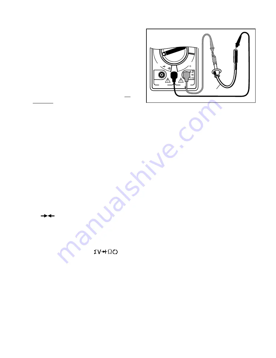
2. Insert BLACK test lead into COM test
lead jack (see Fig. 25).
3. Insert RED test lead into
test
lead jack.
4. Connect RED test lead to one end of
ignition wire and BLACK test lead to
other end.
5. Turn multimeter rotary switch to 200K
Ω
range.
6. View reading on display while flexing
ignition wire and boot in several places.
• Typical resistance range is 3K
Ω
to 50K
Ω
or approximately 10K
Ω
per foot of wire.
• Refer to vehicle service manual for your
vehicles resistance range.
• As you flex ignition wire, the display
should remain steady.
7. Test Results
Good Ignition Wire:
Display reading is
within manufacturers specification and re-
mains steady while wire is flexed.
Bad Ignition Wire:
Display reading errati-
cally changes as ignition wire is flexed or
display reading is not within manufactur-
ers specification.
Fig. 25
Black
Spark Plug Wire
Red


