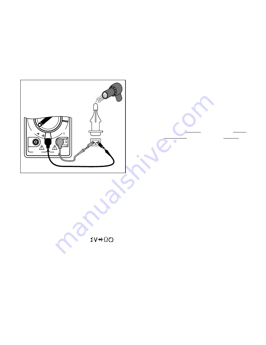
Temperature Type Sensors
30
1. If engine is HOT let it COOL down be-
fore proceeding.
Make sure all engine and transmission
fluids are at outside air temperature before
proceeding with this test!
2. Insert BLACK test lead into COM test
lead jack.
3. Insert RED test lead into
test
lead jack.
4. Disconnect wiring harness from sen-
sor.
5. If testing Intake Air Temperature Sen-
sor - Remove it from vehicle.
All other temperature sensors can remain
on vehicle for testing.
6. Connect RED test lead to either sensor
pin.
7. Connect BLACK test lead to remaining
sensor pin.
8. Turn multimeter rotary switch to de-
A temperature sensor is a thermistor or a
resistor whose resistance changes with tem-
perature. The hotter the sensor gets, the lower
the resistance becomes. Typical thermistor
applications are engine coolant sensors, in-
take air temperature sensors, transmission
fluid temperature sensors, and oil tempera-
ture sensors.
Test Procedure (see Fig. 31):
250V MAX
15A MAX
FUSED
COM
DC
15A
20M
200
K
20K
2K
200
8CYL
6CYL
TACH
X10
5CYL
4CYL
8CYL
OHMS
15
A
Fig. 31
Red
Black
Hair Dryer
Typical
Intake Air
Temperature
Sensor
sired OHM range.
If the approximate resistance is unknown,
start at the largest OHM range and de-
crease to the appropriate range as re-
quired. (See Setting the Range on page 6)
9. View and record reading on display.
10.Disconnect multimeter test leads from
sensor and reconnect sensor wiring.
This step does not apply to intake air
temperature sensors. For intake air tem-
perature sensors, leave multimeter test
leads still connected to sensor.
11.Heat up sensor.
If testing Intake Air Temperature Sensor:
• To heat up sensor dip sensor tip into
boiling water, or...
• Heat tip with a lighter if sensor tip is metal
or a hair dryer if sensor tip is plastic.
• View and record smallest reading on
display as sensor is heated.
• You may need to decrease the range to
get a more accurate reading.
For all other temperature sensors:
• Start engine and let idle until upper ra-
diator hose is warm.
• Turn ignition key OFF.
• Disconnect sensor wiring harness and
reconnect multimeter test leads.
• View and record reading on display.
12.Test Results.
Good Sensor:
• Temperature sensors HOT resistance is
at least 300
Ω
less than its COLD resis-
tance.
• The key point is that the COLD resistance
decreases with increasing temperature.
Bad Sensor:
• There is no change between the tem-
perature sensors HOT resistance from
the COLD resistance.
• The temperature sensor is an open or a
short circuit.


