Installation and Commissioning Guide - Bulkhead 2 Split System
Doc. No. 9590-5011
Ver. 1 211217
9
Installation and Commissioning Guide
Bulkhead Split System
08. Indoor Units Parts
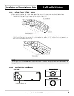
Drain hose
Refrigerant connecting pipe
Air outlet
Air inlet
Air filter*
screw*
Air filter*
NOTE
*Filter is inserted into the flange subassembly through
the bottom side and locked by screw on both sides.
WARNING
• Securely install the indoor unit on a structure that can sustain its weight. If the structure is too weak the unit may fall
causing personal injury, unit and property damage or death.
•
DO NOT
install the indoor unit in the bathroom or laundry room as excessive moisture can short the unit and corrode
the wiring.
CAUTION
• Install the equipment's cables and wires at least 1m from televisions or radios to prevent static or image distortion.
• DO NOT
install the unit in the following locations:
• In areas with oil drilling or fracking
• In areas with caustic gases in the air, such as near hot spring
• In enclosed spaces, such as cabinets
• In areas with strong electromagnetic waves
• In areas that store flammable materials or gas
• In rooms with high humidity, such as bathrooms or laundry rooms
Select Installation Location
The indoor unit should be installed in the location that meets the following requirements:
•
There is enough room for installation and maintenance.
•
There is enough room for the connecting pipe and drainpipe.
•
The ceiling is horizontal and its structure can sustain the weight of the indoor unit.
•
The air inlet and outlet are not impeded.
•
The airflow can fill the entire room.
•
There is no direct radiation from heaters.
SERVICE ACCESS AREAS
AIRFLOW
SIDE CLEARANCE: 200 mm OR MORE
600mm x 600mm
Checking Orifice
AIRFLOW
SIDE CLEARANCE: 300 mm OR MORE
> 300mm
> 20mm
> 20mm
> 2
300mm
(When no ceiling)
B
Floor
NOTE
It is strongly encouraged to have a removable
service access panel underneath the indoor
unit to carry out maintenance and repair.

