Page 29
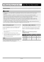
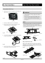
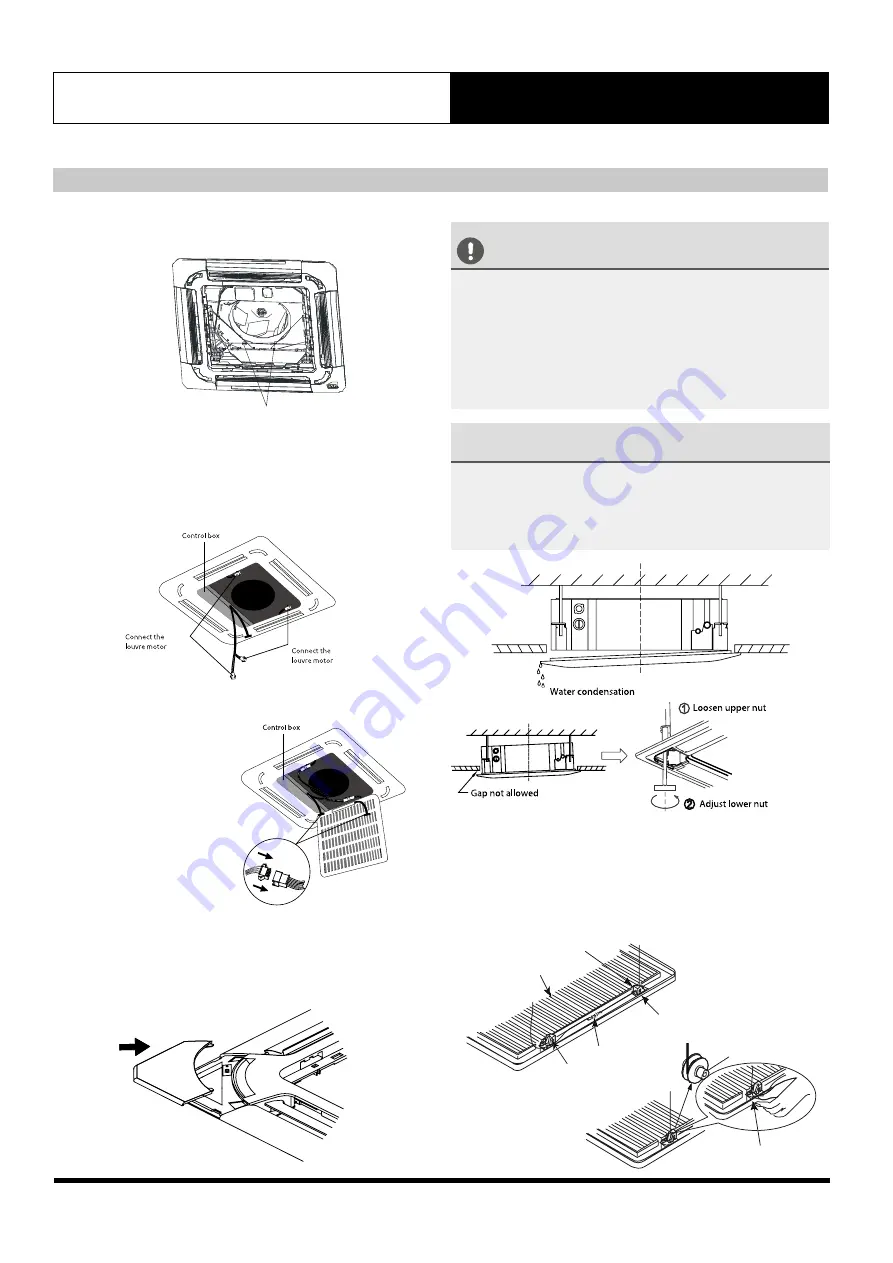
4. Remove styrofoam stops from inside the fan.
5. Connect the two louvre motor connections to the
corresponding wires in the control box.
6. Connect the display panel cable to the corresponding
wire on the main body.
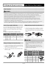
7. Fasten the installation covers at all four corners by
pushing them inwards. (See Fig. 10.9)
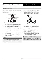
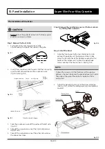
3. Use 2 screws to screw in the panel into the indoor unit.
(See Fig 10.6)
The Installation of the Panel
10. Panel Installation
Super Slim Four-Way Cassette
Fig. 10.8
Fig. 10.7
CAUTION
•
Failure to tighten screws can cause water leakage.
(See Fig 10.10)
•
If the unit is not hung correctly and gap a exists,
the unit’s height must be adjusted to ensure proper
function. The unit’s height can be adjusted by
loosening the upper nut, and adjusting the lower nut.
(See Fig 10.11)
NOTE
If the height of the indoor unit needs to be adjusted, you
can do so through the openings at the panel’s four
corners. Make sure that the internal wiring and drainpipe
are not affected by this adjustment.
Fig. 10.9
Fig. 10.10
Fig. 10.11
Two Screws
Fig. 10.6
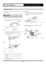
Pass the suspension wire through
the gap at this side
Pass the wire through
the gap
Pulley
Pulley
Grille
Hang the wire on the
pulley in case of falling
Link Spring
Fig. 10.12
Step 4: Install the front Grille
Make sure the suspension wire can be hung correctly on
the pulley. Pass through the suspension wire to the side of
pulley and hang it on the pulley. Make sure the link spring is
in the between of the two pulley.
Fig. 10.13
Summary of Contents for Cascade CRE-071AS
Page 39: ...Page 39 ...

