Installation and Commissioning Guide
Classic 2 Outdoor Units
Installation and Commissioning Guide - Classic 2 Split Ducted Outdoor Unit
Doc. No.0525-073 Ver. 8 210414
33
15.05. Demand Response Management
These products are compliant to AS/NZS 4755.3.1
DR
M
C
ontr
ol Inputs
+12V/COM
DRM 3/COMP
DRM 2/FAN
DRM 1/HEAT
ODU CPU
BOARD
DE
M
AND RE
SP
ONSE
M
ANA
GE
MENT
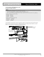
1. Route DRM input cables into the Unit (as per previous wiring installation procedure)
2. Connect cables into terminals (as shown above and as per wiring diagram provided with the unit).
Demand
Management Mode
Description Of Mode
Allowable Range (%)
Operating Mode
DRM1
Compressor Off Mode
Compressor ONLY will cycle Off & remain Off for
the entire Demand Response event. All other
functions will operate as normal (i.e. Indoor Fan)
DRM2
Maximum 50% power use mode
with 0 to <50% allowable power use range
Compressor 0 to <50% operation range for the
total Demand Response event.
DRM3
Maximum 75% power use mode
with 0 to <75% allowable power use range
Compressor 0 to <75% operation range for the
total Demand Response event.
NOTE
Demand Response Management is not
applicable when using third party control.
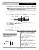
DEMAND RESPONSE ENABLING DEVICE CIRCUIT DIAGRAM
ODU CPU
BOARD
DEMAND
RESPONSE
MANAGEMENT
DEMAND RESPONSE
ENABLING DEVICE (DRED)
AS4755 COMPLIANT
DEVICE (OPTIONAL)
DRED VOLTAGE
FREE CONTACTS
+12V/COM
DRM 1/HEAT
DRM 2/FAN
DRM 3/COMP


